Benefits & Trade-Offs
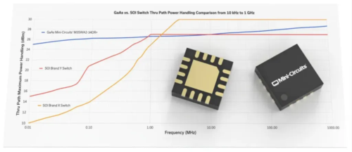
One key advantage of blocking switch matrices over other configurations is the inherent performance of the discrete RF switches used in their construction. A blocking switch matrix built using mechanical switches is the closest approximation to physically connecting and disconnecting a cable between 2 devices. Mini-Circuits has mechanical switch components available with very low insertion loss for the active path, very high isolation for the disconnected path, high power rating and exceptionally wide bandwidths, from DC up to as high as 50 GHz, making them ideal for blocking matrix designs.
While mechanical switches are optimized for reliability with switching lifetimes specified on the order of millions of switching cycles, the moving parts will wear out eventually, so for applications requiring an exceptional number of switch operations (for example, semi-conductor testing), a solid-state blocking matrix may be more appropriate. Matrices built with solid-state switches also have the advantages of a physically smaller package for the matrix and a faster switching time (subject to delays in the Ethernet / USB control interface).
Mini-Circuits has a range of high-performance solid-state switch modules available for use in switch matrix designs, which successfully combine some of the performance benefits more often associated with mechanical switches, including very high isolation and ultra-wide bandwidths.
The notable trade-off for a blocking switch matrix configuration in comparison to the other matrix types summarized below is the limitation that each path can only provide a one-to-one connection. For applications requiring multiple signals to be routed to the same port simultaneously, a non-blocking or full fan-out configuration would be required.
Applications
The one-to-one nature of blocking switch matrices, with minimum loss on active paths and maximum isolation of disconnected paths, makes the configuration perfectly suited to expansion of automated test and measurement environments. The matrix can be used to switch signal sources, signal analyzers and any other test equipment between input / output ports of 1 or more devices under test (DUT), with minimum interference in the measurement. The ability to automate this switching through software, rather than requiring someone to be available to change the physical cable connections, allows for test sequences to be automated and run unattended, maximizing throughput and utilization of test equipment.
A special case of this is Mini-Circuits’ ZTVX series 2 x n blocking switch matrices (available from 2 x 8 up to 2 x 32). The 2 “input” ports can be connected to a standard 2-port VNA to expand the capability of the test setup, either for testing of multiple 2-port devices, or for testing of devices with a larger number of ports.
Mini-Circuits’ Solutions
Mini-Circuits’ ZT-8X8B and ZT-8X8B-1835 are summarized below as examples of 8 x 8 blocking switch matrices. ZT-8X8B operates from 10 MHz to 6 GHz, using solid-state switches for high-throughput, fast-switching applications. ZT-8X8B-1835 offers the same configuration implemented with mechanical switches, offering a wider bandwidth, from DC to 18 GHz and very low insertion loss. Both models can be controlled via Ethernet or USB, using the included GUI or comprehensive API for automation in most modern programming environments.