Mini-Circuits Directional, Bi-Directional & Dual-Directional Couplers to 65 GHz with Local Engineering Support in Israel
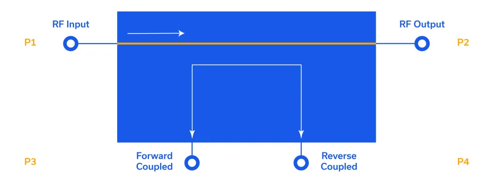
MCDI offers a broad selection of Mini-Circuits RF, microwave and millimeter-wave couplers for signal sampling, RF power monitoring, reflected-power measurement, feedback, test and measurement and other RF signal-chain applications.
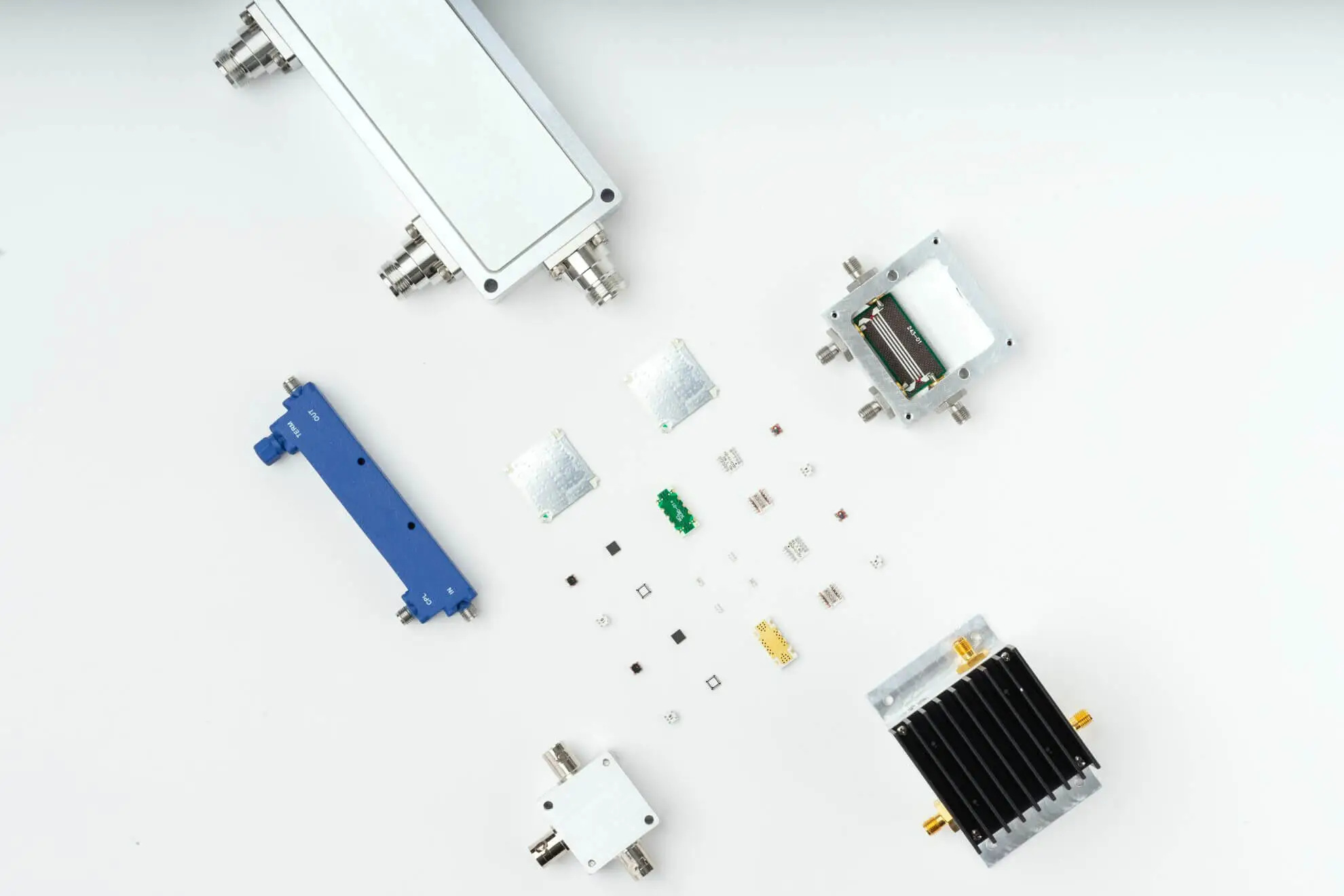
The portfolio includes directional couplers, bi-directional couplers, dual-directional couplers and RF power taps, with surface-mount, connectorized and MMIC configurations for both 50 Ω and selected 75 Ω systems.
Mini-Circuits coupler solutions cover frequencies from DC through 65 GHz, using technologies including transformer, LTCC, MMIC, microstrip/stripline and directional-bridge designs. High-power solutions are also available for demanding transmitter, amplifier and RF test applications.
MCDI’s Application Engineering team in Israel can assist you in selecting the appropriate RF coupler according to frequency, coupling factor, directivity, mainline loss, VSWR, power handling, impedance, DC pass-through requirements and mechanical interface.
10.1 dB SMT Bi-Directional Coupler, 800 - 2500 MHz
SMT
50
800
2500
10.10
1.00
22
1.05
32.26
24
Bi-Directional
LTCC
DC Passthrough
0.30 x 0.32 x 0.07
2024-12-03-01.01.06.253000
BDCA1-10-40+
10 dB SMT Bi-Directional Coupler, 1600 - 4000 MHz
SMT
50
1,600
4000
10.00
1.05
21
1.10
26.44
12
Bi-Directional
LTCC
DC Passthrough
0.30 x 0.27 x 0.05
2024-12-03-01.01.06.253000
BDCA-15-25+
15 dB SMT Bi-Directional Coupler, 800 - 2500 MHz
SMT
50
800
2500
15.00
0.50
27
1.20
20.83
23
Bi-Directional
LTCC
DC Passthrough
0.30 x 0.27 x 0.05
2024-12-03-01.01.06.253000
BDCA1-6-22+
6.5 dB SMT Bi-Directional Coupler, 950 - 2200 MHz
SMT
50
950
2200
6.50
1.70
25
1.10
26.44
37
Bi-Directional
LTCC
DC Passthrough
0.30 x 0.27 x 0.05
2024-12-03-01.01.06.253000
BDCA-16-30+
15.5 dB SMT Bi-Directional Coupler, 1800 - 4200 MHz
SMT
50
1,800
4200
15.50
0.40
23
1.30
17.69
20
Bi-Directional
LTCC
DC Passthrough
0.30 x 0.27 x 0.05
2024-12-03-01.01.06.253000
BDCA1-7-33+
7 dB SMT Bi-Directional Coupler, 1600 - 3300 MHz
SMT
50
1,600
3300
7.00
1.60
23
1.15
23.13
24
Bi-Directional
LTCC
DC Passthrough
0.30 x 0.27 x 0.05
2024-12-03-01.01.06.253000
BDCA-6-16+
6.3 dB SMT Bi-Directional Coupler, 800 - 1600 MHz
SMT
50
800
1600
6.30
1.60
24
1.05
32.26
65
Bi-Directional
LTCC
DC Passthrough
0.30 x 0.27 x 0.05
2024-12-03-01.01.06.253000
BDCA-7-25+
7.1 dB SMT Bi-Directional Coupler, 1200 - 2500 MHz
SMT
50
1,200
2500
7.10
1.60
22
1.05
32.26
35
Bi-Directional
LTCC
DC Passthrough
0.30 x 0.27 x 0.05
2024-12-03-01.01.06.253000
BDCN-10-25+
10.2 dB SMT Bi-Directional Coupler, 824 - 2525 MHz
SMT
50
824
2525
10.20
1.00
17
1.20
20.83
15
Bi-Directional
LTCC
-
0.13 x 0.06 x 0.04
2024-12-03-01.01.06.253000
BDCN-14-22+
13.8 dB SMT Bi-Directional Coupler, 1930 - 2710 MHz
SMT
50
1,930
2170
13.80
0.50
23
1.25
19.08
16
Bi-Directional
LTCC
-
0.13 x 0.06 x 0.04
2024-12-03-01.01.06.253000
BDCN-14-342+
14 dB SMT Bi-Directional Coupler, 1700 - 3400 MHz
SMT
50
1,700
3400
14.00
0.40
14
1.22
20.08
16
Bi-Directional
LTCC
-
0.13 x 0.06 x 0.04
2024-12-03-01.01.06.253000
BDCN-15-25+
14.5 dB SMT Bi-Directional Coupler, 824 - 2525 MHz
SMT
50
824
2525
14.50
0.60
13
1.20
20.83
16
Bi-Directional
LTCC
DC Passthrough
0.13 x 0.06 x 0.04
2024-12-03-01.01.06.253000
BDCN-17-25+
16.8 dB SMT Bi-Directional Coupler, 824 - 2525 MHz
SMT
50
824
2525
16.80
0.60
13
1.20
20.83
16
Bi-Directional
LTCC
DC Passthrough
0.13 x 0.06 x 0.04
2024-12-03-01.01.06.253000
BDCN-20-13+
20.7 dB SMT Bi-Directional Coupler, 360 - 1000 MHz
SMT
50
360
1000
20.70
0.20
12
1.08
28.30
16
Bi-Directional
LTCC
-
0.13 x 0.06 x 0.04
2024-12-03-01.01.06.253000
BDCN-7-25+
8.2 dB SMT Bi-Directional Coupler, 824 - 2525 MHz
SMT
50
824
2525
8.20
1.30
20
1.15
23.13
15
Bi-Directional
LTCC
-
0.13 x 0.06 x 0.04
2024-12-03-01.01.06.253000
CPL-20-14+
19.2 dB SMT Bi-Directional Coupler, 9200 - 10500 MHz
SMT
50
9,200
10500
19.20
0.20
16
1.20
20.83
16
Bi-Directional
Microstrip / Stripline
DC Passthrough
.25 x .25 x .02
2024-12-03-01.01.06.253000
D17IA+
17.1 dB SMT Directional Coupler, 2300 - 2600 MHz
SMT
50
2,300
2600
17.10
0.40
14
1.10
26.44
4
Directional
MMIC
-
0.12 x 0.12 x 0.06
2024-12-03-01.01.06.253000
D17W+
16-26 dB SMT Directional Coupler, 700 - 3500 MHz
SMT
50
700
3500
16.00
0.40
14
1.25
19.08
4
Directional
MMIC
-
0.12 x 0.12 x 0.06
2024-12-03-01.01.06.253000
D18PA+
19.3 dB SMT Directional Coupler, 1700 - 2000 MHz
SMT
50
1,700
2000
19.30
0.30
16
1.10
26.44
4
Directional
MMIC
-
0.12 x 0.12 x 0.06
2024-12-03-01.01.06.253000
D19GA+
20.7 dB SMT Directional Coupler, 1400 - 1700 MHz
SMT
50
1,400
1700
20.70
0.30
17
1.10
26.44
4
Directional
MMIC
-
0.12 x 0.12 x 0.06
2024-12-03-01.01.06.253000
D20C+
19.2 dB SMT Directional Coupler, 810 - 960 MHz
SMT
50
810
960
19.20
0.30
15
1.10
26.44
1
Directional
MMIC
-
0.12 x 0.12 x 0.06
2024-12-03-01.01.06.253000
DBTC-10-13+
10.3 dB SMT Directional Coupler, 5 - 1000 MHz
SMT
50
5
1000
10.30
1.40
18
1.30
17.69
1
Directional
Transformer
-
0.15 x 0.15 x 0.15
2024-12-03-01.01.06.253000
DBTC-10-13L+
10.3 dB SMT Directional Coupler, 5 - 1000 MHz
SMT
50
5
1000
10.30
1.40
18
1.30
17.69
1
Directional
Transformer
-
0.17 x 0.15 x 0.16
2024-12-03-01.01.06.253000
DBTC-10-13LX+
10.3 dB SMT Directional Coupler, 5 - 1000 MHz
SMT
50
5
1000
10.30
1.40
18
1.30
17.69
1
Directional
Transformer
-
.166 x .150 x .155
2024-12-03-01.01.06.253000
DBTC-10-13X+
10.3 dB SMT Directional Coupler, 5 - 1000 MHz
SMT
50
5
1000
10.30
1.40
18
1.30
17.69
1
Directional
Transformer
-
.150 x .150 x .150
2024-12-03-01.01.06.253000
DBTC-10-4-75+
10.5 dB SMT Directional Coupler, 5 - 1000 MHz
SMT
75
5
1000
10.50
0.70
20
1.30
17.69
1
Directional
Transformer
-
0.15 x 0.15 x 0.15
2024-12-03-01.01.06.253000
DBTC-10-4-75L+
10.5 dB SMT Directional Coupler, 5 - 1000 MHz
SMT
75
5
1000
10.50
0.70
20
1.30
17.69
1
Directional
Transformer
-
0.17 x 0.15 x 0.16
2024-12-03-01.01.06.253000
DBTC-10-4-75LX+
10.5 dB SMT Directional Coupler, 5 - 1000 MHz
SMT
75
5
1000
10.50
0.70
20
1.30
17.69
1
Directional
Transformer
-
.166 x .150 x .155
2024-12-03-01.01.06.253000
DBTC-10-4-75X+
10.5 dB SMT Directional Coupler, 5 - 1000 MHz
SMT
75
5
1000
10.50
0.70
20
1.30
17.69
1
Directional
Transformer
-
.150 x .150 x .150
2024-12-03-01.01.06.253000
DBTC-12-4+
12.2 dB SMT Directional Coupler, 5 - 1000 MHz
SMT
50
5
1000
12.20
0.70
21
1.30
17.69
1
Directional
Transformer
-
0.15 x 0.15 x 0.15
2024-12-03-01.01.06.253000
DBTC-12-4-75+
12 dB SMT Directional Coupler, 5 - 1200 MHz
SMT
75
5
1200
12.00
1.10
19
1.30
17.69
0
Directional
Transformer
-
0.15 x 0.15 x 0.15
2024-12-03-01.01.06.253000
DBTC-12-4-75L+
12 dB SMT Directional Coupler, 5 - 1200 MHz
SMT
75
5
1200
12.00
1.10
19
1.30
17.69
0
Directional
Transformer
-
0.17 x 0.15 x 0.16
2024-12-03-01.01.06.253000
DBTC-12-4-75LX+
12 dB SMT Directional Coupler, 5 - 1200 MHz
SMT
75
5
1200
12.00
1.10
19
1.30
17.69
0
Directional
Transformer
-
.166 x .150 x .155
2024-12-03-01.01.06.253000
DBTC-12-4-75X+
12 dB SMT Directional Coupler, 5 - 1200 MHz
SMT
75
5
1200
12.00
1.10
19
1.30
17.69
0
Directional
Transformer
-
.150 x .150 x .150
2024-12-03-01.01.06.253000
DBTC-12-4L+
12.2 dB SMT Directional Coupler, 5 - 1000 MHz
SMT
50
5
1000
12.20
0.70
21
1.30
17.69
1
Directional
Transformer
-
0.17 x 0.15 x 0.16
2024-12-03-01.01.06.253000
DBTC-12-4X+
12.2 dB SMT Directional Coupler, 5 - 1000 MHz
SMT
50
5
1000
12.20
0.70
21
1.30
17.69
1
Directional
Transformer
-
.150 x .150 x .150
2024-12-03-01.01.06.253000
DBTC-13-4+
13 dB SMT Directional Coupler, 5 - 1000 MHz
SMT
50
5
1000
13.00
0.70
18
1.30
17.69
1
Directional
Transformer
-
0.15 x 0.15 x 0.15
2024-12-03-01.01.06.253000
DBTC-13-4L+
13 dB SMT Directional Coupler, 5 - 1000 MHz
SMT
50
5
1000
13.00
0.70
18
1.30
17.69
1
Directional
Transformer
-
0.17 x 0.15 x 0.16
2024-12-03-01.01.06.253000
DBTC-13-4LX+
13 dB SMT Directional Coupler, 5 - 1000 MHz
SMT
50
5
1000
13.00
0.70
18
1.30
17.69
1
Directional
Transformer
-
.166 x .150 x .155
2024-12-03-01.01.06.253000
DBTC-13-4X+
13 dB SMT Directional Coupler, 5 - 1000 MHz
SMT
50
5
1000
13.00
0.70
18
1.30
17.69
1
Directional
Transformer
-
.150 x .150 x .150
2024-12-03-01.01.06.253000
DBTC-13-5-75+
13.2 dB SMT Directional Coupler, 5 - 1500 MHz
SMT
75
5
1500
13.20
0.70
19
1.30
17.69
1
Directional
Transformer
-
0.15 x 0.15 x 0.15
2024-12-03-01.01.06.253000
DBTC-13-5-75L+
13.2 dB SMT Directional Coupler, 5 - 1500 MHz
SMT
75
5
1500
13.20
1.40
19
1.30
17.69
1
Directional
Transformer
-
0.17 x 0.15 x 0.16
2024-12-03-01.01.06.253000
DBTC-13-5-75LX+
13.2 dB SMT Directional Coupler, 5 - 1500 MHz
SMT
75
5
1500
13.20
1.40
19
1.30
17.69
1
Directional
Transformer
-
.166 x .150 x .155
2024-12-03-01.01.06.253000
DBTC-13-5-75X+
13.2 dB SMT Directional Coupler, 5 - 1500 MHz
SMT
75
5
1500
13.20
0.70
19
1.30
17.69
1
Directional
Transformer
-
.150 x .150 x .150
2024-12-03-01.01.06.253000
DBTC-16-5-75+
16.3 dB SMT Directional Coupler, 5 - 1500 MHz
SMT
75
5
1500
16.30
1.30
21
1.30
17.69
1
Directional
Transformer
-
0.15 x 0.15 x 0.15
2024-12-03-01.01.06.253000
DBTC-16-5-75L+
16.3 dB SMT Directional Coupler, 5 - 1500 MHz
SMT
75
5
1500
16.30
1.30
21
1.30
17.69
1
Directional
Transformer
-
0.17 x 0.15 x 0.16
2024-12-03-01.01.06.253000
DBTC-16-5-75LX+
16.3 dB SMT Directional Coupler, 5 - 1500 MHz
SMT
75
5
1500
16.30
1.30
21
1.30
17.69
1
Directional
Transformer
-
.166 x .150 x .155
2024-12-03-01.01.06.253000
DBTC-16-5-75X+
16.3 dB SMT Directional Coupler, 5 - 1500 MHz
SMT
75
5
1500
16.30
1.30
21
1.30
17.69
1
Directional
Transformer
-
.150 x .150 x .150
2024-12-03-01.01.06.254000
DBTC-17-5+
17.2 dB SMT Directional Coupler, 50 - 2000 MHz
SMT
50
50
2000
17.20
1.00
20
1.20
20.83
2
Directional
Transformer
-
0.15 x 0.15 x 0.15
2024-12-03-01.01.06.254000
DBTC-17-5L+
17.2 dB SMT Directional Coupler, 50 - 2000 MHz
SMT
50
50
2000
17.20
1.00
20
1.20
20.83
2
Directional
Transformer
-
0.17 x 0.15 x 0.16
2024-12-03-01.01.06.254000
DBTC-17-5LX+
17.2 dB SMT Directional Coupler, 50 - 2000 MHz
SMT
50
50
2000
17.20
1.00
20
1.20
20.83
2
Directional
Transformer
-
.166 x .150 x .155
2024-12-03-01.01.06.254000
DBTC-18-4-75+
18.2 dB SMT Directional Coupler, 5 - 1000 MHz
SMT
75
5
1000
18.20
0.80
21
1.30
17.69
1
Directional
Transformer
-
0.15 x 0.15 x 0.15
2024-12-03-01.01.06.254000
DBTC-18-4-75L+
18.2 dB SMT Directional Coupler, 5 - 1000 MHz
SMT
75
5
1000
18.20
0.80
21
1.30
17.69
1
Directional
Transformer
-
0.17 x 0.15 x 0.16
2024-12-03-01.01.06.254000
DBTC-18-4-75LX+
18.2 dB SMT Directional Coupler, 5 - 1000 MHz
SMT
75
5
1000
18.20
0.80
21
1.30
17.69
1
Directional
Transformer
-
.166 x .150 x .155
2024-12-03-01.01.06.254000
DBTC-18-4-75X+
18.2 dB SMT Directional Coupler, 5 - 1000 MHz
SMT
75
5
1000
18.20
0.80
21
1.30
17.69
1
Directional
Transformer
-
.150 x .150 x .150
2024-12-03-01.01.06.254000
DBTC-20-4+
20.4 dB SMT Directional Coupler, 20 - 1000 MHz
SMT
50
20
1000
20.40
0.70
21
1.20
20.83
1
Directional
Transformer
-
0.15 x 0.15 x 0.15
2024-12-03-01.01.06.254000
DBTC-20-4-75+
20.5 dB SMT Directional Coupler, 5 - 1250 MHz
SMT
75
5
1250
20.50
0.80
19
1.40
15.56
1
Directional
Transformer
-
0.15 x 0.15 x 0.15
2024-12-03-01.01.06.254000
DBTC-20-4-75X+
20.5 dB SMT Directional Coupler, 5 - 1250 MHz
SMT
75
5
1250
20.50
0.80
19
1.40
15.56
1
Directional
Transformer
-
.150 x .150 x .150
2024-12-03-01.01.06.254000
DBTC-20-4L+
20.4 dB SMT Directional Coupler, 20 - 1000 MHz
SMT
50
20
1000
20.40
0.70
21
1.20
20.83
1
Directional
Transformer
-
0.17 x 0.15 x 0.16
2024-12-03-01.01.06.254000
DBTC-20-4LX+
20.4 dB SMT Directional Coupler, 20 - 1000 MHz
SMT
50
20
1000
20.40
0.70
21
1.20
20.83
1
Directional
Transformer
-
.166 x .150 x .155
2024-12-03-01.01.06.254000
DBTC-20-4X+
20.4 dB SMT Directional Coupler, 20 - 1000 MHz
SMT
50
20
1000
20.40
0.70
21
1.20
20.83
1
Directional
Transformer
-
.150 x .150 x .150
2024-12-03-01.01.06.254000
DBTC-6-4-75+
6.8 dB SMT Directional Coupler, 5 - 1250 MHz
SMT
75
5
1250
6.80
2.20
17
1.40
15.56
1
Directional
Transformer
-
0.15 x 0.15 x 0.15
2024-12-03-01.01.06.254000
DBTC-6-4-75L+
6.8 dB SMT Directional Coupler, 5 - 1250 MHz
SMT
75
5
1250
6.80
2.20
17
1.40
15.56
1
Directional
Transformer
-
0.17 x 0.15 x 0.16
2024-12-03-01.01.06.254000
DBTC-6-4-75LX+
6.8 dB SMT Directional Coupler, 5 - 1250 MHz
SMT
75
5
1250
6.80
2.20
17
1.40
15.56
1
Directional
Transformer
-
.166 x .150 x .155
2024-12-03-01.01.06.254000
DBTC-6-4-75X+
6.8 dB SMT Directional Coupler, 5 - 1250 MHz
SMT
75
5
1250
6.80
2.20
17
1.40
15.56
1
Directional
Transformer
-
.150 x .150 x .150
2024-12-03-01.01.06.254000
DBTC-7-152+
7 dB SMT Directional Coupler, 10 - 1500 MHz
SMT
50
10
1500
7.00
2.20
32
1.40
15.56
0
Directional
Transformer
-
0.15 x 0.15 x 0.15
2024-12-03-01.01.06.254000
DBTC-7-152L+
7 dB SMT Directional Coupler, 10 - 1500 MHz
SMT
50
10
1500
7.00
2.20
32
1.40
15.56
0
Directional
Transformer
-
0.17 x 0.15 x 0.16
2024-12-03-01.01.06.254000
DBTC-7-152LX+
7 dB SMT Directional Coupler, 10 - 1500 MHz
SMT
50
10
1500
7.00
2.20
32
1.40
15.56
0
Directional
Transformer
-
.166 x .150 x .155
2024-12-03-01.01.06.254000
DBTC-7-152X+
7 dB SMT Directional Coupler, 10 - 1500 MHz
SMT
50
10
1500
7.00
2.20
32
1.40
15.56
0
Directional
Transformer
-
.150 x .150 x .150
2024-12-03-01.01.06.254000
DBTC-9-4+
9 dB SMT Directional Coupler, 5 - 1000 MHz
SMT
50
5
1000
9.00
1.20
18
1.30
17.69
1
Directional
Transformer
-
0.15 x 0.15 x 0.15
2024-12-03-01.01.06.254000
DBTC-9-4-75+
9.3 dB SMT Directional Coupler, 5 - 1200 MHz
SMT
75
5
1200
9.30
1.30
20
1.30
17.69
0
Directional
Transformer
-
0.15 x 0.15 x 0.15
2024-12-03-01.01.06.254000
DBTC-9-4-75L+
9.3 dB SMT Directional Coupler, 5 - 1200 MHz
SMT
75
5
1200
9.30
1.30
20
1.30
17.69
0
Directional
Transformer
-
0.17 x 0.15 x 0.16
2024-12-03-01.01.06.254000
DBTC-9-4-75LX+
9.3 dB SMT Directional Coupler, 5 - 1200 MHz
SMT
75
5
1200
9.30
1.30
20
1.30
17.69
0
Directional
Transformer
-
.166 x .150 x .155
2024-12-03-01.01.06.254000
DBTC-9-4-75X+
9.3 dB SMT Directional Coupler, 5 - 1200 MHz
SMT
75
5
1200
9.30
1.30
20
1.30
17.69
0
Directional
Transformer
-
.150 x .150 x .150
2024-12-03-01.01.06.254000
DBTC-9-4L+
9 dB SMT Directional Coupler, 5 - 1000 MHz
SMT
50
5
1000
9.00
1.20
18
1.30
17.69
1
Directional
Transformer
-
0.17 x 0.15 x 0.16
2024-12-03-01.01.06.254000
DBTC-9-4LX+
9 dB SMT Directional Coupler, 5 - 1000 MHz
SMT
50
5
1000
9.00
1.20
18
1.30
17.69
1
Directional
Transformer
-
.166 x .150 x .155
2024-12-03-01.01.06.254000
DBTC-9-4X+
9 dB SMT Directional Coupler, 5 - 1000 MHz
SMT
50
5
1000
9.00
1.20
18
1.30
17.69
1
Directional
Transformer
-
.150 x .150 x .150
2024-12-03-01.01.06.254000
DCW-22-332+
22 dB SMT Directional Coupler, 1200 - 3300 MHz
SMT
50
1,200
3300
22.00
0.40
12
1.20
20.83
2
Directional
LTCC
-
.063 x .031 x .024
2024-12-03-01.01.06.254000
DCW-30-272+
30 dB SMT Directional Coupler, 700 - 2700 MHz
SMT
50
700
2700
30.00
0.20
14
1.20
20.83
2
Directional
LTCC
-
.063 x .031 x .024
2024-12-03-01.01.06.254000
JDC-10-2+
10 dB SMT Directional Coupler, 5 - 750 MHz
SMT
50
5
750
10.00
1.00
20
1.13
24.29
1
Directional
Transformer
-
0.31 x 0.28 x 0.23
2024-12-03-01.01.06.254000
JDC-10-4+
10.5 dB SMT Directional Coupler, 5 - 1000 MHz
SMT
50
5
1000
10.50
1.30
23
1.15
23.13
1
Directional
Transformer
-
0.31 x 0.28 x 0.23
2024-12-03-01.01.06.254000
JDC-20-1W+
19.5 dB SMT Directional Coupler, 50 - 750 MHz
SMT
50
50
750
19.50
0.50
22
1.20
20.83
0
Directional
Transformer
-
0.31 x 0.28 x 0.23
2024-12-03-01.01.06.254000
JDC-20-2+
20.5 dB SMT Directional Coupler, 400 - 900 MHz
SMT
50
400
900
20.50
0.20
19
1.15
23.13
2
Directional
Transformer
-
0.31 x 0.28 x 0.23
2024-12-03-01.01.06.254000
JDC-20-3-75+
19.2 dB SMT Directional Coupler, 2 - 250 MHz
SMT
75
2
250
19.20
0.40
30
1.10
26.44
1
Directional
Transformer
-
0.31 x 0.28 x 0.23
2024-12-03-01.01.06.254000
JDC-20-5+
20.5 dB SMT Directional Coupler, 50 - 1500 MHz
SMT
50
50
1500
20.50
1.00
22
1.20
20.83
0
Directional
Transformer
-
0.31 x 0.28 x 0.23
2024-12-03-01.01.06.254000
JDC-6-1+
6.5 dB SMT Directional Coupler, 5 - 400 MHz
SMT
50
5
400
6.50
2.00
25
1.25
19.08
0
Directional
Transformer
-
0.31 x 0.28 x 0.23
2024-12-03-01.01.06.254000
JYDC-23-1HP+
23.5 dB SMT Directional Coupler, 30 - 500 MHz
SMT
50
30
500
23.50
0.40
23
1.10
26.44
10
Directional
Transformer
-
0.52 x 0.40 x 0.23
2024-12-03-01.01.06.254000
LRDC-10-1
10.7 dB SMT Directional Coupler, 5 - 500 MHz
SMT
50
5
500
10.70
0.90
31
1.20
20.83
1
Directional
Transformer
-
0.40 x 0.31 x 0.20
2024-12-03-01.01.06.254000
LRDC-10-1+
10.7 dB SMT Directional Coupler, 5 - 500 MHz
SMT
50
5
500
10.70
0.90
31
1.20
20.83
1
Directional
Transformer
-
0.40 x 0.31 x 0.20
2024-12-03-01.01.06.254000
LRDC-10-1J+
10.7 dB SMT Directional Coupler, 5 - 500 MHz
SMT
50
5
500
10.70
1.20
30
1.20
20.83
1
Directional
Transformer
-
0.40 x 0.31 x 0.23
2024-12-03-01.01.06.254000
LRDC-20-2+
20.5 dB SMT Directional Coupler, 300 - 1100 MHz
SMT
50
300
1100
20.50
0.25
17
1.20
20.83
2
Directional
Transformer
-
0.40 x 0.31 x 0.20
2024-12-03-01.01.06.254000
MBD-20-63HP+
20 dB SMT Bi-Directional Coupler, 5000 - 6000 MHz
SMT
50
5,000
6000
20.00
0.18
20
1.10
26.44
20
Bi-Directional
Microstrip / Stripline
DC Passthrough
0.24 x 0.12 x 0.04
2024-12-03-01.01.06.254000
PDC-10-1+
11.5 dB Plug-in Directional Coupler, 0.5 - 500 MHz
Plug-in
50
0
500
11.50
0.65
32
1.20
20.83
3
Directional
Transformer
-
0.80 x 0.40 x 0.40
2024-12-03-01.01.06.254000
PDC-10-5+
10.5 dB Plug-in Directional Coupler, 1 - 2000 MHz
Plug-in
50
1
2000
10.50
1.30
30
1.30
17.69
0
Directional
Transformer
-
0.80 x 0.40 x 0.40
2024-12-03-01.01.06.254000
PDC-15-6+
15 dB Plug-in Directional Coupler, 0.01 - 35 MHz
Plug-in
50
0
35
15.00
0.20
35
1.15
23.13
4
Directional
Transformer
-
0.80 x 0.40 x 0.40
2024-12-03-01.01.06.254000
PDC-20-3+
19.5 dB Plug-in Directional Coupler, 0.2 - 250 MHz
Plug-in
50
0
250
19.50
0.25
33
1.20
20.83
4
Directional
Transformer
-
0.80 x 0.40 x 0.40
2024-12-03-01.01.06.254000
PDC-20-3BD+
19.5 dB Plug-in Bi-Directional Coupler, 0.2 - 250 MHz
Plug-in
50
0
250
19.50
0.25
40
1.10
26.44
4
Bi-Directional
Transformer
-
0.80 x 0.40 x 0.40
2024-12-03-01.01.06.254000
PDC20-400HP+
21.5 dB Plug-in Directional Coupler, 40 - 400 MHz
Plug-in
50
40
400
21.50
0.20
30
1.10
26.44
10
Directional
Transformer
-
0.80 x 0.40 x 0.40
2024-12-03-01.01.06.254000
RDC-10-122-75X+
10 dB SMT Directional Coupler, 5 - 1250 MHz
SMT
75
5
1250
10.00
1.20
20
1.22
20.08
1
Directional
Transformer
-
.25 x .28 x .14
2024-12-03-01.01.06.255000
SCBD-10-63HP+
10 dB SMT Bi-Directional Coupler, 50 - 6000 MHz
SMT
50
50
6000
10.00
0.90
17
1.22
20.08
100
Bi-Directional
Microstrip / Stripline
DC Passthrough
.70 x .32 x .20
2024-12-03-01.01.06.255000
SCBD-16-63HP+
16.2 dB SMT Bi-Directional Coupler, 50 - 6000 MHz
SMT
50
50
6000
16.20
0.45
23
1.22
20.08
100
Bi-Directional
Microstrip / Stripline
DC Passthrough
.70 x .32 x .20
2024-12-03-01.01.06.255000
SCBD-20-272HP+
18.6 dB SMT Bi-Directional Coupler, 1750 - 2750 MHz
SMT
50
1,750
2750
18.60
0.25
24
1.08
28.30
100
Bi-Directional
Microstrip / Stripline
DC Passthrough
.70 x .32 x .20
2024-12-03-01.01.06.255000
SEDC-10-63+
10 dB SMT Directional Coupler, 50 - 6000 MHz
SMT
50
50
6000
10.00
4.00
27
1.50
13.98
1
Directional
Transformer
-
.93 x 1.26 x .39
2024-12-03-01.01.06.255000
SYBD-10-63HP+
11.8 dB SMT Bi-Directional Coupler, 2700 - 6000 MHz
SMT
50
2,700
6000
11.80
0.60
20
1.20
20.83
25
Bi-Directional
Microstrip / Stripline
DC Passthrough
0.70 x 0.32 x 0.13
2024-12-03-01.01.06.255000
SYBD-16-53HP+
16.3 dB SMT Bi-Directional Coupler, 2700 - 5000 MHz
SMT
50
2,700
5000
16.30
0.20
18
1.20
20.83
25
Bi-Directional
Microstrip / Stripline
DC Passthrough
0.70 x 0.32 x 0.13
2024-12-03-01.01.06.255000
SYBD-18-142HP+
19.5 dB SMT Bi-Directional Coupler, 960 - 1400 MHz
SMT
50
960
1400
19.50
0.15
26
1.10
26.44
50
Bi-Directional
Microstrip / Stripline
DC Passthrough
0.70 x 0.32 x 0.13
2024-12-03-01.01.06.255000
SYBD-26-13HP+
26.8 dB SMT Bi-Directional Coupler, 800 - 1000 MHz
SMT
50
800
1000
26.80
0.03
29
1.05
32.26
100
Bi-Directional
Microstrip / Stripline
DC Passthrough
0.70 x 0.32 x 0.13
2024-12-03-01.01.06.255000
SYBD-26-62HP+
27.2 dB SMT Bi-Directional Coupler, 400 - 610 MHz
SMT
50
400
610
27.20
0.08
24
1.05
32.26
100
Bi-Directional
Microstrip / Stripline
DC Passthrough
0.70 x 0.32 x 0.13
2024-12-03-01.01.06.255000
SYBD-28-62HP+
28.8 dB SMT Bi-Directional Coupler, 400 - 610 MHz
SMT
50
400
610
28.80
0.03
27
1.10
26.44
100
Bi-Directional
Microstrip / Stripline
DC Passthrough
0.70 x 0.32 x 0.13
2024-12-03-01.01.06.255000
SYBD-30-62HP+
32.5 dB SMT Bi-Directional Coupler, 400 - 610 MHz
SMT
50
400
610
32.50
0.02
30
1.05
32.26
100
Bi-Directional
Microstrip / Stripline
DC Passthrough
0.70 x 0.32 x 0.13
2024-12-03-01.01.06.255000
SYD-20-33+
20.8 dB SMT Directional Coupler, 30 - 3000 MHz
SMT
50
30
3000
20.80
1.60
15
1.20
20.83
1
Directional
Transformer
-
0.50 x 0.38 x 0.25
2024-12-03-01.01.06.255000
SYDC-10-42HP+
10 dB SMT Directional Coupler, 10 - 400 MHz
SMT
50
10
400
10.00
0.40
18
1.10
26.44
16
Directional
Transformer
-
.500 x .620 x .36
2024-12-03-01.01.06.255000
SYDC-10-52VHP+
10 dB SMT Bi-Directional Coupler, 30 - 512 MHz
SMT
50
30
512
10.00
1.00
19
1.18
21.66
35
Bi-Directional
Transformer
-
.750 x .520 x .43
2024-12-03-01.01.06.255000
SYDC-18-23+
18 dB SMT Bi-Directional Coupler, 10 - 2000 MHz
SMT
50
10
2000
18.00
0.70
20
1.25
19.08
2
Bi-Directional
Transformer
-
0.50 x 0.38 x 0.25
2024-12-03-01.01.06.255000
SYDC-19-52HP+
19.5 dB SMT Bi-Directional Coupler, 30 - 512 MHz
SMT
50
30
512
19.50
0.35
25
1.11
25.66
50
Bi-Directional
Transformer
-
.433 x .690 x .415
2024-12-03-01.01.06.255000
SYDC-19-52VHP+
19.5 dB SMT Bi-Directional Coupler, 30 - 512 MHz
SMT
50
30
512
19.50
0.35
25
1.10
26.44
60
Bi-Directional
Transformer
-
.750 x .520 x .43
2024-12-03-01.01.06.255000
SYDC-20-13HP+
20 dB SMT Bi-Directional Coupler, 40 - 1000 MHz
SMT
50
40
1000
20.00
0.40
28
1.55
13.32
10
Bi-Directional
Transformer
-
0.50 x 0.38 x 0.25
2024-12-03-01.01.06.255000
SYDC-20-22HP+
20.1 dB SMT Bi-Directional Coupler, 3 - 200 MHz
SMT
50
3
200
20.10
0.10
24
1.10
26.44
25
Bi-Directional
Transformer
-
0.50 x 0.38 x 0.25
2024-12-03-01.01.06.255000
SYDC-20-31HP+
20.5 dB SMT Bi-Directional Coupler, 1.5 - 30 MHz
SMT
50
1
30
20.50
0.06
33
1.13
24.29
50
Bi-Directional
Transformer
-
.500 x .620 x .36
2024-12-03-01.01.06.255000
SYDC-20-61HP+
20 dB SMT Bi-Directional Coupler, 1.5 - 60 MHz
SMT
50
1
60
20.00
0.10
35
1.05
32.26
15
Bi-Directional
Transformer
-
0.50 x 0.38 x 0.25
2024-12-03-01.01.06.255000
SYDC-20-61VHP+
20 dB SMT Directional Coupler, 1.5 - 60 MHz
SMT
50
1
60
20.00
0.10
30
1.02
40.09
40
Directional
Transformer
-
.433 x .630 x .355
2024-12-03-01.01.06.255000
SYDC-20-62HP+
19.8 dB SMT Bi-Directional Coupler, 10 - 540 MHz
SMT
50
10
540
19.80
0.20
28
1.10
26.44
25
Bi-Directional
Transformer
-
0.50 x 0.38 x 0.25
2024-12-03-01.01.06.255000
SYDC-30-12HP+
29 dB SMT Bi-Directional Coupler, 20 - 100 MHz
SMT
50
20
100
29.00
0.06
30
1.03
36.61
55
Bi-Directional
Transformer
-
0.50 x 0.38 x 0.25
2024-12-03-01.01.06.255000
TCD-10-122-75X+
10 dB SMT Directional Coupler, 5 - 1250 MHz
SMT
75
5
1250
10.00
1.50
15
1.17
22.12
1
Directional
Transformer
-
.150 x .150 x .160
2024-12-03-01.01.06.255000
TCD-10-1W+
10.3 dB SMT Directional Coupler, 10 - 750 MHz
SMT
50
10
750
10.30
1.20
18
1.30
17.69
1
Directional
Transformer
-
0.16 x 0.15 x 0.16
2024-12-03-01.01.06.255000
TCD-10-1W-75+
10.5 dB SMT Directional Coupler, 10 - 750 MHz
SMT
75
10
750
10.50
1.40
18
1.30
17.69
1
Directional
Transformer
-
0.16 x 0.15 x 0.16
2024-12-03-01.01.06.255000
TCD-10-1W-75X+
10.5 dB SMT Directional Coupler, 10 - 750 MHz
SMT
75
10
750
10.50
1.40
18
1.30
17.69
1
Directional
Transformer
-
.160 x .150 x .160
2024-12-03-01.01.06.255000
TCD-10-4-75+
9.9 dB SMT Directional Coupler, 5 - 1000 MHz
SMT
75
5
1000
9.90
1.10
20
1.25
19.08
1
Directional
Transformer
-
0.15 x 0.15 x 0.16
2024-12-03-01.01.06.255000
TCD-10-4-75X+
9.9 dB SMT Directional Coupler, 5 - 1000 MHz
SMT
75
5
1000
9.90
1.10
20
1.25
19.08
1
Directional
Transformer
-
.150 x .150 x .160
2024-12-03-01.01.06.255000
TCD-12-222X+
12.6 dB SMT Directional Coupler, 5 - 2250 MHz
SMT
50
5
2250
12.60
2.00
10
1.43
15.04
1
Directional
Transformer
-
.160 x .150 x .160
2024-12-03-01.01.06.255000
TCD-13-122-75X+
12.7 dB SMT Directional Coupler, 5 - 1250 MHz
SMT
75
5
1250
12.70
1.00
15
1.17
22.12
1
Directional
Transformer
-
.160 x .150 x .160
2024-12-03-01.01.06.255000
TCD-13-4+
13 dB SMT Directional Coupler, 5 - 1000 MHz
SMT
50
5
1000
13.00
0.70
18
1.20
20.83
1
Directional
Transformer
-
0.16 x 0.15 x 0.16
2024-12-03-01.01.06.255000
TCD-13-4-75+
13 dB SMT Directional Coupler, 5 - 1000 MHz
SMT
75
5
1000
13.00
0.80
15
1.20
20.83
1
Directional
Transformer
-
0.16 x 0.15 x 0.16
2024-12-03-01.01.06.255000
TCD-13-4-75X+
13 dB SMT Directional Coupler, 5 - 1000 MHz
SMT
75
5
1000
13.00
0.80
15
1.20
20.83
1
Directional
Transformer
-
.160 x .150 x .160
2024-12-03-01.01.06.255000
TCD-13-4X+
13 dB SMT Directional Coupler, 5 - 1000 MHz
SMT
50
5
1000
13.00
0.70
18
1.20
20.83
1
Directional
Transformer
-
.160 x .150 x .160
2024-12-03-01.01.06.255000
TCD-16-122-75X+
16.5 dB SMT Directional Coupler, 5 - 1250 MHz
SMT
75
5
1250
16.50
1.50
22
1.33
16.98
1
Directional
Transformer
-
.160 x .150 x .160
2024-12-03-01.01.06.255000
TCD-16-12W-75X+
16 dB SMT Directional Coupler, 5 - 1218 MHz
SMT
75
5
1218
16.00
0.90
16
1.30
17.69
1
Directional
Transformer
-
.160 x .150 x .160
2024-12-03-01.01.06.255000
TCD-16-23-75X+
16.5 dB SMT Directional Coupler, 5 - 2000 MHz
SMT
75
5
2000
16.50
1.30
22
1.20
20.83
1
Directional
Transformer
-
.160 x .150 x .160
2024-12-03-01.01.06.255000
TCD-18-122-75X+
17.5 dB SMT Directional Coupler, 5 - 1250 MHz
SMT
75
5
1250
17.50
1.00
22
1.17
22.12
1
Directional
Transformer
-
.160 x .150 x .160
2024-12-03-01.01.06.255000
TCD-18-4+
17.9 dB SMT Directional Coupler, 5 - 1000 MHz
SMT
50
5
1000
17.90
0.70
20
1.20
20.83
1
Directional
Transformer
-
0.16 x 0.15 x 0.16
2024-12-03-01.01.06.255000
TCD-18-4-75+
18 dB SMT Directional Coupler, 10 - 1000 MHz
SMT
75
10
1000
18.00
0.70
22
1.20
20.83
1
Directional
Transformer
-
0.16 x 0.15 x 0.16
2024-12-03-01.01.06.255000
TCD-18-4-75X+
18 dB SMT Directional Coupler, 10 - 1000 MHz
SMT
75
10
1000
18.00
0.70
22
1.20
20.83
1
Directional
Transformer
-
.160 x .150 x .160
2024-12-03-01.01.06.255000
TCD-18-4X+
17.9 dB SMT Directional Coupler, 5 - 1000 MHz
SMT
50
5
1000
17.90
0.70
20
1.20
20.83
1
Directional
Transformer
-
.160 x .150 x .160
2024-12-03-01.01.06.255000
TCD-20-4+
20 dB SMT Directional Coupler, 5 - 1000 MHz
SMT
50
5
1000
20.00
0.40
21
1.20
20.83
1
Directional
Transformer
-
0.16 x 0.15 x 0.16
2024-12-03-01.01.06.255000
TCD-20-4-75+
20 dB SMT Directional Coupler, 40 - 1200 MHz
SMT
75
40
1200
20.00
0.60
23
1.15
23.13
1
Directional
Transformer
-
0.16 x 0.15 x 0.16
2024-12-03-01.01.06.255000
TCD-20-4-75X+
20 dB SMT Directional Coupler, 40 - 1200 MHz
SMT
75
40
1200
20.00
0.60
23
1.15
23.13
1
Directional
Transformer
-
.160 x .150 x .160
2024-12-03-01.01.06.256000
TCD-20-4X+
20 dB SMT Directional Coupler, 5 - 1000 MHz
SMT
50
5
1000
20.00
0.40
21
1.20
20.83
1
Directional
Transformer
-
.160 x .150 x .160
2024-12-03-01.01.06.256000
TCD-6-122-75X+
6.7 dB SMT Directional Coupler, 5 - 1250 MHz
SMT
75
5
1250
6.70
2.30
12
1.43
15.04
0
Directional
Transformer
-
.160 x .150 x .160
2024-12-03-01.01.06.256000
TCD-9-1W+
8.9 dB SMT Directional Coupler, 5 - 2000 MHz
SMT
50
5
2000
8.90
1.50
17
1.50
13.98
1
Directional
Transformer
-
0.16 x 0.15 x 0.16
2024-12-03-01.01.06.256000
TCD-9-1W-75+
8.9 dB SMT Directional Coupler, 5 - 2000 MHz
SMT
75
5
2000
8.90
1.80
15
1.50
13.98
1
Directional
Transformer
-
0.16 x 0.15 x 0.16
2024-12-03-01.01.06.256000
TCD-9-1W-75X+
8.9 dB SMT Directional Coupler, 5 - 2000 MHz
SMT
75
5
2000
8.90
1.80
15
1.50
13.98
1
Directional
Transformer
-
.160 x .150 x .160
2024-12-03-01.01.06.256000
TCD-9-1WX+
8.9 dB SMT Directional Coupler, 5 - 2000 MHz
SMT
50
5
2000
8.90
1.50
17
1.50
13.98
1
Directional
Transformer
-
.160 x .150 x .160
2024-12-03-01.01.06.256000
TDC-10-1+
10 dB Plug-in Directional Coupler, 1 - 400 MHz
Plug-in
50
1
400
10.00
1.00
30
1.50
13.98
2
Directional
Transformer
-
0.50 x 0.23 x 0.26
2024-12-03-01.01.06.256000
TDC-10-2+
11 dB Plug-in Directional Coupler, 5 - 1000 MHz
Plug-in
50
5
1000
11.00
1.50
25
1.50
13.98
0
Directional
Transformer
-
0.50 x 0.23 x 0.26
2024-12-03-01.01.06.256000
Z30-16-5-75+
16.5 dB Connector Directional Coupler, 5 - 1500 MHz
Conn.
75
5
1500
16.50
1.10
24
1.30
17.69
1
Directional
Transformer
-
1.25 x 1.25 x 0.75
2024-12-03-01.01.06.256000
Z30-18-4-75+
18.5 dB Conn. Directional Coupler, 5 - 1000 MHz
Conn.
75
5
1000
18.50
0.85
23
1.30
17.69
1
Directional
Transformer
-
1.25 x 1.25 x 0.75
2024-12-03-01.01.06.256000
ZABDC10-25HP-S
10 dB Conn. Bi-Directional Coupler, 1500 - 2500 MHz
Conn.
50
1,500
2500
10.00
0.55
26
1.10
26.44
10
Bi-Directional
Microstrip / Stripline
DC Passthrough
2.00 x 2.00 x 0.75
2024-12-03-01.01.06.256000
ZABDC20-182H-S+
20.5 dB Conn. Bi-Directional Coupler, 700 - 1800 MHz
Conn.
50
700
1800
20.50
0.20
25
1.08
28.30
50
Bi-Directional
Microstrip / Stripline
DC Passthrough
2.00 x 2.00 x .88
2024-12-03-01.01.06.256000
ZABDC20-232H+
20.5 dB Conn. Bi-Directional Coupler, 800 - 2300 MHz
Conn.
50
800
2300
20.50
0.23
20
1.15
23.13
50
Bi-Directional
Microstrip / Stripline
DC Passthrough
2.00 x 2.00 x .88
2024-12-03-01.01.06.256000
ZABDC20-2400-S+
19.5 dB Conn. Bi-Directional Coupler, 1500 - 2400 MHz
Conn.
50
1,500
2400
19.50
0.30
25
1.20
20.83
10
Bi-Directional
Microstrip / Stripline
DC Passthrough
2.00 x 2.00 x 0.75
2024-12-03-01.01.06.256000
ZABDC20-252H+
21.7 dB Conn. Bi-Directional Coupler, 800 - 2500 MHz
Conn.
50
800
2500
21.70
0.20
28
1.05
32.26
50
Bi-Directional
Microstrip / Stripline
DC Passthrough
2.00 x 2.00 x .88
2024-12-03-01.01.06.256000
ZABDC20-322H-S+
20.5 dB Conn. Bi-Directional Coupler, 1700 - 3200 MHz
Conn.
50
1,700
3200
20.50
0.25
21
1.10
26.44
50
Bi-Directional
Microstrip / Stripline
DC Passthrough
2.00 x 2.00 x .88
2024-12-03-01.01.06.256000
ZABDC50-150HP+
50 dB Conn. Bi-Directional Coupler, 0.4 - 15 MHz
Conn.
50
0
15
50.00
0.01
30
1.03
36.61
100
Bi-Directional
Microstrip / Stripline
-
2.00 x 2.00 x 0.95
2024-12-03-01.01.06.256000
ZADC-10-10-S
10 dB Conn. Directional Coupler, 800 - 1000 MHz
Conn.
50
800
1000
10.00
0.85
22
1.16
22.61
5
Directional
Microstrip / Stripline
DC Passthrough
2.00 x 2.00 x 0.75
2024-12-03-01.01.06.256000
ZADC-10-17-S+
9.8 dB Conn. Directional Coupler, 1000 - 1700 MHz
Conn.
50
1,000
1700
9.80
0.80
25
1.20
20.83
5
Directional
Microstrip / Stripline
DC Passthrough
2.00 x 2.00 x 0.75
2024-12-03-01.01.06.256000
ZADC-10-17W-S+
10.2 dB Conn. Directional Coupler, 800 - 1900 MHz
Conn.
50
800
1900
10.20
0.80
24
1.20
20.83
5
Directional
Microstrip / Stripline
DC Passthrough
2.00 x 2.00 x 0.75
2024-12-03-01.01.06.256000
ZADC-10-63-S+
11.7 dB Conn. Directional Coupler, 2500 - 6000 MHz
Conn.
50
2,500
6000
11.70
0.60
23
1.11
25.66
4
Directional
Microstrip / Stripline
DC Passthrough
2.00 x 2.00 x .75
2024-12-03-01.01.06.256000
ZADC-13-73-S+
13 dB Conn. Directional Coupler, 2600 - 7000 MHz
Conn.
50
2,600
7000
13.00
0.80
18
1.20
20.83
4
Directional
Microstrip / Stripline
DC Passthrough
2.00 x 2.00 x .75
2024-12-03-01.01.06.256000
ZADC-17-14HP-S
16.4 dB Conn. Directional Coupler, 500 - 1350 MHz
Conn.
50
500
1350
16.40
0.80
29
1.06
30.71
10
Directional
LTCC
DC Passthrough
2.00 x 2.00 x 0.75
2024-12-03-01.01.06.256000
ZADC-20-10+
20 dB Conn. Directional Coupler, 800 - 1000 MHz
Conn.
50
800
1000
20.00
0.40
21
1.18
21.66
5
Directional
Microstrip / Stripline
DC Passthrough
2.00 x 2.00 x 0.75
2024-12-03-01.01.06.256000
ZADC-20-18-75+
19.8 dB Conn. Directional Coupler, 800 - 1750 MHz
Conn.
75
800
1750
19.80
0.40
22
1.20
20.83
1
Directional
Transformer
-
2.00 x 2.00 x 0.75
2024-12-03-01.01.06.256000
ZADC-40-27HP+
40 dB Conn. Directional Coupler, 1400 - 2700 MHz
Conn.
50
1,400
2700
40.00
0.19
25
1.20
20.83
40
Directional
Microstrip / Stripline
DC Passthrough
2.00 x 2.00 x 0.75
2024-12-03-01.01.06.256000
ZADC-6-2G-5W-S+
6.7 dB Conn. Directional Coupler, 800 - 2000 MHz
Conn.
50
800
2000
6.70
1.60
25
1.15
23.13
5
Directional
Microstrip / Stripline
DC Passthrough
2.00 x 2.00 x 0.75
2024-12-03-01.01.06.256000
ZARC-20-52+
20 dB Conn. RF Tap100 - 550 MHz
Conn.
50
100
550
20.00
0.90
21
0.00
0.00
16
RF Tap
Microstrip / Stripline
-
3.00 x 2.06 x 2.03
2024-12-03-01.01.06.256000
ZARC-25-252-S+
25 dB Conn. RF Tap Coupler, 550 - 2500 MHz
Conn.
50
550
2500
25.00
0.15
27
0.00
0.00
100
RF Tap
Microstrip / Stripline
-
3.00 x 2.06 x 2.03
2024-12-03-01.01.06.256000
ZARC-25-551-S+
25 dB Conn. RF Tap Coupler, 100 - 550 MHz
Conn.
50
100
550
25.00
0.12
23
0.00
0.00
100
RF Tap
Microstrip / Stripline
-
3.00 x 2.06 x 2.03
2024-12-03-01.01.06.256000
ZARC-26-12-S+
26 dB Conn. RF Tap Coupler, 20 - 100 MHz
Conn.
50
20
100
26.00
0.06
27
0.00
0.00
100
RF Tap
Microstrip / Stripline
-
3.00 x 2.06 x 2.03
2024-12-03-01.01.06.256000
ZDC-10-1+
11.5 dB Conn. Directional Coupler, 0.5 - 500 MHz
Conn.
50
0
500
11.50
0.65
32
1.20
20.83
3
Directional
Transformer
-
2.25 x 1.38 x 1.24
2024-12-03-01.01.06.256000
ZDC-10-1-75+
10.5 dB Conn. Directional Coupler, 1 - 250 MHz
Conn.
75
1
250
10.50
1.10
30
2.00
9.54
4
Directional
Transformer
-
2.25 x 1.38 x 1.24
2024-12-03-01.01.06.256000
ZDC-20-1+
20 dB Conn. Directional Coupler, 25 - 400 MHz
Conn.
50
25
400
20.00
0.30
35
1.25
19.08
5
Directional
Transformer
-
2.25 x 1.38 x 1.24
2024-12-03-01.01.06.256000
ZDC-20-3
19.5 dB Conn. Directional Coupler, 0.2 - 250 MHz
Conn.
50
0
250
19.50
0.25
33
1.20
20.83
4
Directional
Transformer
-
2.25 x 1.38 x 1.24
2024-12-03-01.01.06.256000
ZDC-20-3-75+
19.5 dB Conn. Directional Coupler, 1 - 150 MHz
Conn.
75
1
150
19.50
0.35
25
2.00
9.54
4
Directional
Transformer
-
2.25 x 1.38 x 1.24
2024-12-03-01.01.06.256000
ZDC-20-3-75-1+
18.6 dB Conn. Directional Coupler, 55 - 90 MHz
Conn.
75
55
90
18.60
0.40
35
1.20
20.83
4
Directional
Transformer
-
2.25 x 1.38 x 1.24
2024-12-03-01.01.06.256000
ZDC-2375
10.5 dB Conn. Directional Coupler, 50 - 100 MHz
Conn.
75
50
100
10.50
1.10
35
1.30
17.69
4
Directional
Transformer
-
2.25 x 1.38 x 1.24
2024-12-03-01.01.06.256000
ZEDC-10-2B
11 dB Conn. Directional Coupler, 1 - 1000 MHz
Conn.
50
1
1000
11.00
1.50
30
1.30
17.69
3
Directional
Transformer
-
1.25 x 0.83 x 0.75
2024-12-03-01.01.06.256000
ZEDC-15-2B
15 dB Conn. Directional Coupler, 1 - 1000 MHz
Conn.
50
1
1000
15.00
0.80
30
1.15
23.13
3
Directional
Transformer
-
1.25 x 0.83 x 0.75
2024-12-03-01.01.06.256000
ZFBDC16-63HP+
16 dB Conn. Bi-Directional Coupler, 700 - 6000 MHz
Conn.
50
700
6000
16.00
0.55
25
1.22
20.08
75
Bi-Directional
Microstrip / Stripline
-
2.00 x 2.00 x .88
2024-12-03-01.01.06.256000
ZFBDC20-13HP+
20 dB Conn. Bi-Directional Coupler, 40 - 1000 MHz
Conn.
50
40
1000
20.00
0.60
22
1.20
20.83
10
Bi-Directional
Transformer
-
2.00 x 2.00 x .88
2024-12-03-01.01.06.256000
ZFBDC20-61HP+
20 dB Conn. Bi-Directional Coupler, 1 - 60 MHz
Conn.
50
1
60
20.00
0.10
30
1.07
29.42
15
Bi-Directional
Transformer
-
2.00 x 2.00 x .88
2024-12-03-01.01.06.256000
ZFBDC20-62HP+
20 dB Conn. Bi-Directional Coupler, 10 - 600 MHz
Conn.
50
10
600
20.00
0.25
25
1.05
32.26
25
Bi-Directional
Transformer
-
2.00 x 2.00 x .88
2024-12-03-01.01.06.256000
ZFBDC20-900HP
20.7 dB Conn. Bi-Directional Coupler, 800 - 900 MHz
Conn.
50
800
900
20.70
0.10
28
1.10
26.44
10
Bi-Directional
Transformer
-
1.25 x 1.25 x 0.75
2024-12-03-01.01.06.256000
ZFDC-10-1+
10.5 dB Conn. Directional Coupler, 1 - 500 MHz
Conn.
50
1
500
10.50
0.80
33
1.20
20.83
3
Directional
Transformer
-
1.25 x 1.25 x 0.75
2024-12-03-01.01.06.256000
ZFDC-10-182+
10.4 dB Conn. Directional Coupler, 10 - 1800 MHz
Conn.
50
10
1800
10.40
1.00
31
1.16
22.61
0
Directional
Transformer
-
1.25 x 1.25 x 0.75
2024-12-03-01.01.06.256000
ZFDC-10-2
10.75 dB Conn. Directional Coupler, 10 - 1000 MHz
Conn.
50
10
1000
10.75
1.20
30
1.50
13.98
3
Directional
Transformer
-
1.25 x 1.25 x 0.75
2024-12-03-01.01.06.257000
ZFDC-10-21
11 dB Conn. Directional Coupler, 1 - 1000 MHz
Conn.
50
1
1000
11.00
1.20
25
1.20
20.83
2
Directional
Transformer
-
1.25 x 1.25 x 0.75
2024-12-03-01.01.06.257000
ZFDC-10-5+
10.8 dB Conn. Directional Coupler, 1 - 2000 MHz
Conn.
50
1
2000
10.80
1.20
30
1.30
17.69
0
Directional
Transformer
-
1.25 x 1.25 x 0.75
2024-12-03-01.01.06.257000
ZFDC-10-6+
11 dB Conn. Directional Coupler, 0.005 - 20 MHz
Conn.
50
0
20
11.00
0.40
40
1.30
17.69
3
Directional
Transformer
-
1.25 x 1.25 x 0.75
2024-12-03-01.01.06.257000
ZFDC-15-10+
15 dB Conn. Directional Coupler, 800 - 1000 MHz
Conn.
50
800
1000
15.00
0.30
23
1.20
20.83
5
Directional
Microstrip / Stripline
DC Passthrough
1.25 x 1.25 x 0.75
2024-12-03-01.01.06.257000
ZFDC-15-6+
15 dB Conn. Directional Coupler, 0.03 - 35 MHz
Conn.
50
0
35
15.00
0.20
35
1.15
23.13
4
Directional
Transformer
-
1.25 x 1.25 x 0.75
2024-12-03-01.01.06.257000
ZFDC-20-3+
19.5 dB Conn. Directional Coupler, 0.2 - 250 MHz
Conn.
50
0
250
19.50
0.25
33
1.20
20.83
4
Directional
Transformer
-
1.25 x 1.25 x 0.75
2024-12-03-01.01.06.257000
ZFDC-20-33+
20.5 dB Conn. Directional Coupler, 20 - 3000 MHz
Conn.
50
20
3000
20.50
0.90
15
1.50
13.98
1
Directional
Transformer
-
1.25 x 1.25 x 0.75
2024-12-03-01.01.06.257000
ZFDC-20-3-75+
19.3 dB Conn. Directional Coupler, 10 - 250 MHz
Conn.
75
10
250
19.30
0.30
29
1.20
20.83
2
Directional
Transformer
-
1.25 x 1.25 x 0.75
2024-12-03-01.01.06.257000
ZFDC-20-4
19.5 dB Conn. Directional Coupler, 1 - 1000 MHz
Conn.
50
1
1000
19.50
0.40
27
1.10
26.44
2
Directional
Transformer
-
1.25 x 1.25 x 0.75
2024-12-03-01.01.06.257000
ZFDC-20-4+
19.5 dB Conn. Directional Coupler, 1 - 1000 MHz
Conn.
50
1
1000
19.50
0.40
27
1.10
26.44
2
Directional
Transformer
-
1.25 x 1.25 x 0.75
2024-12-03-01.01.06.257000
ZFDC-20-4L
20.2 dB Conn. Directional Coupler, 10 - 1000 MHz
Conn.
50
10
1000
20.20
0.30
30
1.10
26.44
1
Directional
Transformer
-
1.25 x 1.25 x 0.75
2024-12-03-01.01.06.257000
ZFDC-20-5+
19.5 dB Conn. Directional Coupler, 0.1 - 2000 MHz
Conn.
50
0
2000
19.50
0.70
27
1.20
20.83
2
Directional
Transformer
-
1.25 x 1.25 x 0.75
2024-12-03-01.01.06.257000
ZFDC-20-50+
19.5 dB Conn. Directional Coupler, 20 - 2000 MHz
Conn.
50
20
2000
19.50
0.70
25
1.25
19.08
1
Directional
Transformer
-
1.25 x 1.25 x 0.75
2024-12-03-01.01.06.257000
ZGBDC35-93HP+
34.5 dB Conn. Bi-Directional Coupler, 900 - 9000 MHz
Conn.
50
900
9000
34.50
0.10
19
1.20
20.83
250
Bi-Directional
Microstrip / Stripline
DC Passthrough
3.85 x 1.10 x .80
2024-12-03-01.01.06.257000
ZGDC35-93HP+
35 dB Conn. Directional Coupler, 900 - 9000 MHz
Conn.
50
900
9000
35.00
0.10
19
1.25
19.08
250
Directional
Microstrip / Stripline
DC Passthrough
3.85 x 1.10 x .80
2024-12-03-01.01.06.257000
ZHDC-10-63+
10.2 dB Conn. Directional Coupler, 50 - 6000 MHz
Conn.
50
50
6000
10.20
4.00
32
1.20
20.83
1
Directional
Bridge
-
2.50 x 1.40 x 0.88
2024-12-03-01.01.06.257000
ZHDC-10-63-NS+
10.2 dB Conn. Directional Coupler, 50 - 6000 MHz
Conn.
50
50
6000
10.20
4.00
32
1.20
20.83
1
Directional
Bridge
-
2.50 x 1.40 x 0.88
2024-12-03-01.01.06.257000
ZHDC-16-63+
16.7 dB Conn. Directional Coupler, 50 - 6000 MHz
Conn.
50
50
6000
16.70
2.00
32
1.30
17.69
0
Directional
Bridge
-
2.50 x 1.40 x 0.88
2024-12-03-01.01.06.257000
ZHDC-16-63-NS+
16 dB Conn. Directional Coupler, 50 - 6000 MHz
Conn.
50
50
6000
16.00
2.00
24
1.30
17.69
0
Directional
Bridge
-
2.50 x 1.40 x 0.88
2024-12-03-01.01.06.257000
ZMDC-10-1+
11.5 dB Conn. Directional Coupler, 0.5 - 500 MHz
Conn.
50
0
500
11.50
0.65
32
1.20
20.83
3
Directional
Transformer
-
1.50 x 1.13 x 1.00
2024-12-03-01.01.06.257000
ZMDC-20-3+
19.5 dB Conn. Directional Coupler, 0.2 - 250 MHz
Conn.
50
0
250
19.50
0.35
33
1.20
20.83
4
Directional
Transformer
-
1.50 x 1.13 x 1.00
2024-12-03-01.01.06.257000
ZMDC-30-1+
30 dB Conn. Directional Coupler, 0.1 - 250 MHz
Conn.
50
0
250
30.00
0.50
20
1.50
13.98
3
Directional
Transformer
-
1.50 x 1.13 x 1.00
2024-12-03-01.01.06.257000
ZNDC-13-2G-S+
13 dB Conn. Directional Coupler, 800 - 2000 MHz
Conn.
50
800
2000
13.00
0.80
20
1.15
23.13
3
Directional
Transformer
-
2.00 x 1.25 x 0.75
2024-12-03-01.01.06.257000
ZNDC-15-2G-S+
15 dB Conn. Directional Coupler, 800 - 2000 MHz
Conn.
50
800
2000
15.00
0.80
22
1.20
20.83
3
Directional
Transformer
-
2.00 x 1.25 x 0.75
2024-12-03-01.01.06.257000
ZNDC-18-2G-S+
18.2 dB Conn. Directional Coupler, 800 - 2000 MHz
Conn.
50
800
2000
18.20
0.50
25
1.20
20.83
3
Directional
Transformer
-
2.00 x 1.25 x 0.75
2024-12-03-01.01.06.257000
ZNDC-20-2G-S+
19.8 dB Conn. Directional Coupler, 800 - 2000 MHz
Conn.
50
800
2000
19.80
0.50
25
1.15
23.13
3
Directional
Transformer
-
2.00 x 1.25 x 0.75
2024-12-03-01.01.06.257000
ZNDC-23-2G-S+
23 dB Conn. Directional Coupler, 800 - 2000 MHz
Conn.
50
800
2000
23.00
0.50
22
1.20
20.83
3
Directional
Transformer
-
2.00 x 1.25 x 0.75
2024-12-03-01.01.06.257000
ZUDC10-183+
10 dB Conn. Directional Coupler, 500 - 18000 MHz
Conn.
50
500
18000
10.00
1.40
17
1.30
17.69
50
Directional
Microstrip / Stripline
DC Passthrough
6.47 x .73 x .51
2024-12-03-01.01.06.257000
ZUDC20-183+
20 dB Conn. Directional Coupler, 500 - 18000 MHz
Conn.
50
500
18000
20.00
0.90
17
1.30
17.69
50
Directional
Microstrip / Stripline
DC Passthrough
6.47 x .73 x .51
2024-12-03-01.01.06.257000
ZUDC30-183+
30 dB Conn. Directional Coupler, 500 - 18000 MHz
Conn.
50
500
18000
30.00
0.90
16
1.30
17.69
50
Directional
Microstrip / Stripline
DC Passthrough
6.47 x .73 x .51
2024-12-03-01.01.06.257000
ZX30-12-4-S+
12 dB Conn. Directional Coupler, 5 - 1000 MHz
Conn.
50
5
1000
12.00
0.85
25
1.15
23.13
1
Directional
Transformer
-
0.74 x 0.90 x 0.54
2024-12-03-01.01.06.257000
ZX30-13-4-S+
13 dB Conn. Directional Coupler, 5 - 1200 MHz
Conn.
50
5
1200
13.00
0.70
19
1.15
23.13
1
Directional
Transformer
-
0.74 x 0.90 x 0.54
2024-12-03-01.01.06.257000
ZX30-14-972HP+
14 dB Conn. Directional Coupler, 8300 - 9700 MHz
Conn.
50
8,300
9700
14.00
0.80
7
2.30
8.09
20
Directional
Microstrip / Stripline
DC Passthrough
1.04 x 0.60 x 0.75
2024-12-03-01.01.06.257000
ZX30-17-5-S+
17.5 dB Conn. Directional Coupler, 5 - 2000 MHz
Conn.
50
5
2000
17.50
0.85
18
1.30
17.69
1
Directional
Transformer
-
0.74 x 0.90 x 0.54
2024-12-03-01.01.06.257000
ZX30-20-20BD-S+
21 dB Conn. Directional Coupler, 500 - 2000 MHz
Conn.
50
500
2000
21.00
0.20
21
1.20
20.83
2
Directional
Transformer
-
1.04 x 0.60 x 0.75
2024-12-03-01.01.06.257000
ZX30-20-4-S+
20.5 dB Conn. Directional Coupler, 5 - 1000 MHz
Conn.
50
5
1000
20.50
0.35
22
1.11
25.66
1
Directional
Transformer
-
0.74 x 0.90 x 0.54
2024-12-03-01.01.06.257000
ZX30-20-462HP+
19.3 dB Conn. Bi-Directional Coupler, 2600 - 4600 MHz
Conn.
50
2,600
4600
19.30
0.35
25
1.20
20.83
40
Bi-Directional
Microstrip / Stripline
DC Passthrough
1.04 x 0.60 x 0.75
2024-12-03-01.01.06.257000
ZX30-9-4-S+
8.9 dB Conn. Directional Coupler, 5 - 1200 MHz
Conn.
50
5
1200
8.90
1.10
20
1.20
20.83
1
Directional
Transformer
-
0.74 x 0.90 x 0.54
2024-12-03-01.01.06.257000
ZADC-15-252+
15 dB Conn. Directional Coupler, 850 - 2500 MHz
Conn.
50
850
2500
15.00
0.70
14
1.15
23.13
8
Directional
LTCC
DC Passthrough
0.31 x 0.27 x 0.11
2024-12-03-01.01.06.257000
JYDC-7-1HP+
7.3 dB SMT Directional Coupler, 30 - 500 MHz
SMT
50
30
500
7.30
1.40
20
1.25
19.08
5
Directional
Transformer
-
0.50 x 0.40 x 0.23
2024-12-03-01.01.06.257000
ZGBDC20-33H+
20.6 dB Conn. Bi-Directional Coupler, 300 - 3000 MHz
Conn.
50
300
3000
20.60
0.20
23
1.14
23.69
50
Bi-Directional
Microstrip / Stripline
DC Passthrough
5.58 x 2.45 x 1.00
2024-12-03-01.01.06.257000
RBDC-20-63+
20 dB SMT RF Tap Coupler, DC - 6000 MHz
SMT
50
0
6000
20.00
1.35
20
1.30
17.69
0
RF Tap
Microstrip / Stripline
-
0.25 x 0.31 x 0.16
2024-12-03-01.01.06.257000
SYDC-10-62HP+
9.8 dB SMT Bi-Directional Coupler, 10 - 600 MHz
SMT
50
10
600
9.80
0.90
23
1.20
20.83
20
Bi-Directional
Transformer
-
0.50 x 0.38 x 0.25
2024-12-03-01.01.06.257000
TCD-17-282X+
17 dB SMT Directional Coupler, 5 - 2850 MHz
SMT
50
5
2850
17.00
1.90
10
1.40
15.56
1
Directional
Transformer
-
.160 x .150 x .160
2024-12-03-01.01.06.257000
ZUDC10-83-S+
10 dB Conn. Directional Coupler, 300 - 8000 MHz
Conn.
50
300
8000
10.00
0.90
24
1.15
23.13
20
Directional
Microstrip / Stripline
DC Passthrough
6.00 x .73 x .50
2024-12-03-01.01.06.257000
EDC21-24+
21 dB SMT Directional Coupler, 4000 - 20000 MHz
SMT
50
4,000
20000
21.00
0.70
19
1.37
16.13
1
Directional
MMIC
-
0.157 x 0.157 x 0.039
2024-12-03-01.01.06.257000
EDC21-24-D+
21 dB Die Directional Coupler, 4000 - 20000 MHz
Die
50
4,000
20000
21.00
0.70
19
1.37
16.13
1
Directional
MMIC
-
2024-12-03-01.01.06.257000
SYDC-7-651HP+
7.3 dB SMT Directional Coupler, 10 - 650 MHz
SMT
50
10
650
7.30
0.60
21
1.15
23.13
10
Directional
Transformer
-
0.50 x 0.38 x 0.25
2024-12-03-01.01.06.257000
EDC19-KA-D+
18.3 dB Die Directional Coupler, 5000 - 43500 MHz
Die
50
5,000
43500
18.30
0.50
9
1.40
15.56
1
Directional
MMIC
-
2024-12-03-01.01.06.258000
EBDC19-KA-D+
18.7 dB Die Bi-Directional Coupler, 5000 - 43500 MHz
Die
50
5,000
43500
18.70
0.60
10
1.45
14.72
1
Bi-Directional
MMIC
-
2024-12-03-01.01.06.258000
ZDC20-20403-K+
20.0 dB Conn. Directional Coupler, 18000 - 40000 MHz
Conn.
50
18,000
40000
20.00
0.90
12
1.25
19.08
20
Directional
Microstrip / Stripline
DC Passthrough
1.25 x 0.65 x 0.45
2024-12-03-01.01.06.258000
ZDC10-20403-K+
10.0 dB Conn. Directional Coupler, 20000 - 40000 MHz
Conn.
50
20,000
40000
10.00
1.20
13
1.22
20.08
20
Directional
Microstrip / Stripline
DC Passthrough
1.25 x 0.65 x 0.45
2024-12-03-01.01.06.258000
DBTC16-282LX+
16.8 dB SMT Directional Coupler, 5 - 2850 MHz
SMT
50
5
2850
16.80
1.10
18
1.29
17.95
1
Directional
Transformer
-
.166 x .150 x .155
2024-12-03-01.01.06.258000
ZUDC20-02183-S+
20 dB Conn. Directional Coupler, 2000 - 18000 MHz
Conn.
50
2,000
18000
20.00
0.50
20
1.22
20.08
20
Directional
Microstrip / Stripline
DC Passthrough
2.25 x .73 x .50
2024-12-03-01.01.06.258000
ZUDC10-02183-S+
10 dB Conn. Directional Coupler, 2000 - 18000 MHz
Conn.
50
2,000
18000
10.00
0.30
17
1.43
15.04
20
Directional
Microstrip / Stripline
DC Passthrough
2.25 x .73 x .50
2024-12-03-01.01.06.258000
ZUDC15-02183-S+
15 dB Conn. Directional Coupler, 2000 - 18000 MHz
Conn.
50
2,000
18000
15.00
0.30
18
1.25
19.08
20
Directional
Microstrip / Stripline
DC Passthrough
2.25 x .73 x .50
2024-12-03-01.01.06.258000
ZUDC30-02183-S+
30 dB Conn. Directional Coupler, 2000 - 18000 MHz
Conn.
50
2,000
18000
30.00
0.30
17
1.33
16.98
20
Directional
Microstrip / Stripline
DC Passthrough
2.25 x .73 x .50
2024-12-03-01.01.06.258000
ZCDC10-02263S+
10 dB Conn. Directional Coupler, 2000 - 26500 MHz
Conn.
50
2,000
26500
10.00
0.90
27
1.11
25.66
20
Directional
Microstrip / Stripline
DC Passthrough
2.25 x 0.70 x 0.50
2024-12-03-01.01.06.258000
ZCDC10-K0244+
10 dB Conn. Directional Coupler, 2000 - 40000 MHz
Conn.
50
2,000
40000
10.00
1.20
23
1.11
25.66
15
Directional
Microstrip / Stripline
DC Passthrough
2.25 x 0.70 x 0.50
2024-12-03-01.01.06.258000
ZCDC10-K5R44W+
10 dB Conn. Directional Coupler, 500 - 40000 MHz
Conn.
50
500
40000
10.00
1.30
23
1.12
24.94
15
Directional
Microstrip / Stripline
DC Passthrough
4.40 x 0.70 x 0.50
2024-12-03-01.01.06.258000
ZCDC20-02263S+
20 dB Conn. Directional Coupler, 2000 - 26500 MHz
Conn.
50
2,000
26500
20.00
0.50
18
1.33
16.98
20
Directional
Microstrip / Stripline
DC Passthrough
2.25 x 0.70 x 0.50
2024-12-03-01.01.06.258000
ZCDC20-K0244+
20 dB Conn. Directional Coupler, 2000 - 40000 MHz
Conn.
50
2,000
40000
20.00
1.00
20
1.17
22.12
20
Directional
Microstrip / Stripline
DC Passthrough
2.25 x 0.70 x 0.50
2024-12-03-01.01.06.258000
ZUDC20-83-S+
20 dB Conn. Directional Coupler, 300 - 8000 MHz
Conn.
50
300
8000
20.00
0.70
24
1.15
23.13
20
Directional
Microstrip / Stripline
DC Passthrough
6.00 x .73 x .50
2024-12-03-01.01.06.258000
EDC10-273+
10 dB SMT Directional Coupler, 6000 - 26500 MHz
SMT
50
6,000
26500
10.00
1.40
15
1.33
17.00
0
Directional
MMIC
-
0.157 x 0.157 x 0.039
2024-12-03-01.01.06.258000
ZGDC6-372HP+
6 dB Conn. Directional Coupler, 380 - 3700 MHz
Conn.
50
380
3700
6.00
0.20
23
1.09
27.32
250
Directional
Microstrip / Stripline
DC Passthrough
5.93 x 2.40 x 1.00
2024-12-03-01.01.06.258000
ZGDC10-372HP+
10 dB Conn. Directional Coupler, 380 - 3700 MHz
Conn.
50
380
3700
10.00
0.17
23
1.09
27.32
250
Directional
Microstrip / Stripline
DC Passthrough
5.93 x 2.40 x 1.00
2024-12-03-01.01.06.258000
ZGDC20-372HP+
20 dB Conn. Directional Coupler, 300 - 3700 MHz
Conn.
50
300
3700
20.00
0.15
25
1.06
30.71
250
Directional
Microstrip / Stripline
DC Passthrough
5.93 x 2.40 x 1.00
2024-12-03-01.01.06.258000
ZGDC30-372HP+
30 dB Conn. Directional Coupler, 380 - 3700 MHz
Conn.
50
380
3700
30.00
0.16
17
1.07
29.42
250
Directional
Microstrip / Stripline
DC Passthrough
5.93 x 2.40 x 1.00
2024-12-03-01.01.06.258000
ZGBDC6-372HP+
6 dB Conn. Bi-Directional Coupler, 380 - 3700 MHz
Conn.
50
380
3700
6.00
0.29
20
1.14
23.98
250
Bi-Directional
Microstrip / Stripline
DC Passthrough
5.93 x 2.400 x 1.00
2024-12-03-01.01.06.258000
ZGBDC10-372HP+
10 dB Conn. Bi-Directional Coupler, 380 - 3700 MHz
Conn.
50
380
3700
10.00
0.18
20
1.14
23.98
250
Bi-Directional
Microstrip / Stripline
DC Passthrough
5.93 x 2.400 x 1.00
2024-12-03-01.01.06.258000
ZGBDC20-372HP+
20 dB Conn. Bi-Directional Coupler, 300 - 3700 MHz
Conn.
50
300
3700
20.00
0.16
18
1.29
18.00
250
Bi-Directional
Microstrip / Stripline
DC Passthrough
5.93 x 2.400 x 1.00
2024-12-03-01.01.06.258000
ZGBDC30-372HP+
30 dB Conn. Bi-Directional Coupler, 380 - 3700 MHz
Conn.
50
380
3700
30.00
0.20
20
1.22
20.01
250
Bi-Directional
Microstrip / Stripline
DC Passthrough
5.93 x 2.400 x 1.00
2024-12-03-01.01.06.258000
ZNDC-6-122-S+
6 dB Conn. Directional Coupler, 500 - 1200 MHz
Conn.
50
500
1200
6.00
0.50
25
1.20
20.83
2
Directional
Transformer
-
2.00 x 1.25 x 0.75
2024-12-03-01.01.06.258000
ZDC20-20403-V+
20.0 dB Conn. Directional Coupler, 18000 - 40000 MHz
Conn.
50
18,000
40000
20.00
0.90
12
1.25
19.08
20
Directional
Microstrip / Stripline
DC Passthrough
1.25 x 0.65 x 0.45
2024-12-03-01.01.06.258000
EDC10-183+
10 dB SMT Directional Coupler, 6000 - 18000 MHz
SMT
50
6,000
18000
10.00
1.30
16
1.33
17.00
0
Directional
MMIC
-
0.157 x 0.157 x 0.039
2024-12-03-01.01.06.258000
RDC-10-182-75X+
10 dB SMT Directional Coupler, 5 - 1800 MHz
SMT
75
5
1800
10.00
1.30
20
1.20
20.83
1
Directional
Transformer
-
.25 x .28 x .14
2024-12-03-01.01.06.258000
ZCDC10-5R263-S+
10 dB Conn. Directional Coupler, 500 - 26500 MHz
Conn.
50
500
26500
10.00
1.20
22
1.12
24.94
20
Directional
Microstrip / Stripline
DC Passthrough
4.40 x 0.70 x 0.50
2024-12-03-01.01.06.258000
ZCDC30-K0644+
30 dB Conn. Directional Coupler, 6000 - 40000 MHz
Conn.
50
6,000
40000
30.00
0.50
22
1.12
24.94
20
Directional
Microstrip / Stripline
DC Passthrough
1.25 x 0.63 x 0.50
2024-12-03-01.01.06.258000
ZCDC10-K0644+
10 dB Conn. Directional Coupler, 6000 - 40000 MHz
Conn.
50
6,000
40000
10.00
1.00
24
1.12
24.94
17
Directional
Microstrip / Stripline
DC Passthrough
1.25 x 0.63 x 0.50
2024-12-03-01.01.06.258000
ZCDC13-K0244+
13 dB Conn. Directional Coupler, 2000 - 40000 MHz
Conn.
50
2,000
40000
13.00
0.95
24
1.11
25.66
20
Directional
Microstrip / Stripline
DC Passthrough
1.25 x 0.63 x 0.50
2024-12-03-01.01.06.258000
ZCDC13-K1844+
13 dB Conn. Directional Coupler, 18000 - 40000 MHz
Conn.
50
18,000
40000
13.00
0.90
21
1.13
24.29
20
Directional
Microstrip / Stripline
DC Passthrough
1.25 x 0.63 x 0.50
2024-12-03-01.01.06.258000
ZCDC16-K1844+
16 dB Conn. Directional Coupler, 18000 - 40000 MHz
Conn.
50
18,000
40000
16.00
0.70
23
1.10
26.44
20
Directional
Microstrip / Stripline
DC Passthrough
1.25 x 0.63 x 0.50
2024-12-03-01.01.06.258000
ZCDC20-K0644+
20 dB Conn. Directional Coupler, 6000 - 40000 MHz
Conn.
50
6,000
40000
20.00
0.70
22
1.07
29.42
20
Directional
Microstrip / Stripline
DC Passthrough
1.25 x 0.63 x 0.50
2024-12-03-01.01.06.258000
ZCDC20-5R263-S+
20 dB Conn. Directional Coupler, 500 - 26500 MHz
Conn.
50
500
26500
20.00
0.90
25
1.09
27.32
20
Directional
Microstrip / Stripline
DC Passthrough
1.25 x 0.63 x 0.50
2024-12-03-01.01.06.258000
ZCDC30-5R263-S+
30 dB Conn. Directional Coupler, 500 - 26500 MHz
Conn.
50
500
26500
30.00
0.60
28
1.07
29.42
20
Directional
Microstrip / Stripline
DC Passthrough
1.25 x 0.63 x 0.50
2024-12-03-01.01.06.258000
SYBDC-15-13HP+
15.8 dB SMT Bi-Directional Coupler, 100 - 1000 MHz
SMT
50
100
1000
15.80
0.75
20
1.15
23.13
10
Bi-Directional
Transformer
-
0.50 x 0.38 x 0.25
2024-12-03-01.01.06.258000
ZCDC10-01263-S+
10 dB Conn. Directional Coupler, 1000 - 26500 MHz
Conn.
50
1,000
26500
10.00
0.90
21
1.17
22.12
20
Directional
Microstrip / Stripline
DC Passthrough
3.50 x 0.70 x 0.50
2024-12-03-01.01.06.258000
ZCDC10-18263-S+
10 dB Conn. Directional Coupler, 18000 - 26500 MHz
Conn.
50
18,000
26500
10.00
0.90
24
1.15
23.13
20
Directional
Microstrip / Stripline
DC Passthrough
1.25 x 0.63 x 0.50
2024-12-03-01.01.06.258000
ZCDC10-06263-S+
10 dB Conn. Directional Coupler, 6000 - 26500 MHz
Conn.
50
6,000
26500
10.00
1.00
22
1.17
22.12
20
Directional
Microstrip / Stripline
DC Passthrough
1.25 x 0.63 x 0.50
2024-12-03-01.01.06.258000
EDC10-273-D+
10 dB Die Directional Coupler, 6000 - 26500 MHz
Die
50
6,000
26500
10.00
1.40
15
1.33
17.00
0
Directional
MMIC
-
2024-12-03-01.01.06.258000
ZCDC13-5R263-S+
13 dB Conn. Directional Coupler, 500 - 26500 MHz
Conn.
50
500
26500
13.00
1.30
21
1.73
11.46
20
Directional
Microstrip / Stripline
DC Passthrough
4.40 x 0.70 x 0.50
2024-12-03-01.01.06.258000
ZCDC16-5R263-S+
16 dB Conn. Directional Coupler, 500 - 26500 MHz
Conn.
50
500
26500
16.00
1.40
23
1.12
24.94
20
Directional
Microstrip / Stripline
DC Passthrough
4.40 x 0.70 x 0.50
2024-12-03-01.01.06.258000
ZCDC13-K26344+
13 dB Conn. Directional Coupler, 26500 - 40000 MHz
Conn.
50
26,500
40000
13.00
0.90
21
1.22
20.08
20
Directional
Microstrip / Stripline
DC Passthrough
1.25 x 0.63 x 0.50
2024-12-03-01.01.06.258000
ZCDC16-01263-S+
16 dB Conn. Directional Coupler, 1000 - 26500 MHz
Conn.
50
1,000
26500
16.00
0.90
21
1.14
23.69
20
Directional
Microstrip / Stripline
DC Passthrough
3.50 x 0.70 x 0.50
2024-12-03-01.01.06.258000
ZCDC10-K1844+
10 dB Conn. Directional Coupler, 18000 - 40000 MHz
Conn.
50
18,000
40000
10.00
1.20
21
1.22
20.08
17
Directional
Microstrip / Stripline
DC Passthrough
1.25 x 0.63 x 0.50
2024-12-03-01.01.06.258000
ZCDC10-K0144+
10 dB Conn. Directional Coupler, 1000 - 40000 MHz
Conn.
50
1,000
40000
10.00
2.20
16
1.22
20.08
19
Directional
Microstrip / Stripline
DC Passthrough
3.50 x 0.70 x 0.50
2024-12-03-01.01.06.258000
ZCDC13-K0144+
13 dB Conn. Directional Coupler, 1000 - 40000 MHz
Conn.
50
1,000
40000
13.00
1.50
19
1.73
11.46
13
Directional
Microstrip / Stripline
DC Passthrough
3.50 x 0.70 x 0.50
2024-12-03-01.01.06.258000
ZCDC13-01263-S+
13 dB Conn. Directional Coupler, 1000 - 26500 MHz
Conn.
50
1,000
26500
13.00
1.20
21
1.17
22.12
19
Directional
Microstrip / Stripline
DC Passthrough
3.50 x 0.70 x 0.50
2024-12-03-01.01.06.259000
ZCDC20-01263-S+
20 dB Conn. Directional Coupler, 1000 - 26500 MHz
Conn.
50
1,000
26500
20.00
0.90
23
1.12
24.94
20
Directional
Microstrip / Stripline
DC Passthrough
3.50 x 0.70 x 0.50
2024-12-03-01.01.06.259000
ZCDC20-06263-S+
20 dB Conn. Directional Coupler, 6000 - 26500 MHz
Conn.
50
6,000
26500
20.00
0.50
26
1.14
23.69
20
Directional
Microstrip / Stripline
DC Passthrough
1.25 x 0.63 x 0.50
2024-12-03-01.01.06.259000
ZCDC20-18263-S+
20 dB Conn. Directional Coupler, 18000 - 26500 MHz
Conn.
50
18,000
26500
20.00
0.40
24
1.14
23.69
20
Directional
Microstrip / Stripline
DC Passthrough
1.25 x 0.63 x 0.50
2024-12-03-01.01.06.259000
ZCDC20-K1844+
20 dB Conn. Directional Coupler, 18000 - 40000 MHz
Conn.
50
18,000
40000
20.00
0.70
19
1.17
22.12
20
Directional
Microstrip / Stripline
DC Passthrough
1.25 x 0.63 x 0.50
2024-12-03-01.01.06.259000
ZCDC20-K0144+
20 dB Conn. Directional Coupler, 1000 - 40000 MHz
Conn.
50
1,000
40000
20.00
1.20
20
1.20
20.83
20
Directional
Microstrip / Stripline
DC Passthrough
3.50 x 0.70 x 0.50
2024-12-03-01.01.06.259000
ZCDC30-K1844+
30 dB Connector Directional Coupler, 18000 - 40000 MHz
Conn.
50
18,000
40000
30.00
0.60
22
1.15
23.13
20
Directional
Microstrip / Stripline
DC Passthrough
1.25 x 0.63 x 0.50
2024-12-03-01.01.06.259000
ZCDC30-01263-S+
30 dB Connector Directional Coupler, 1000 - 26500 MHz
Conn.
50
1,000
26500
30.00
0.80
23
1.14
23.69
20
Directional
Microstrip / Stripline
DC Passthrough
3.50 x 0.70 x 0.50
2024-12-03-01.01.06.259000
ZCDC30-02263-S+
30 dB Connector Directional Coupler, 2000 - 26500 MHz
Conn.
50
2,000
26500
30.00
0.60
23
1.14
23.69
20
Directional
Microstrip / Stripline
DC Passthrough
2.25 x 0.70 x 0.50
2024-12-03-01.01.06.259000
ZCDC30-06263-S+
30 dB Connector Directional Coupler, 6000 - 26500 MHz
Conn.
50
6,000
26500
30.00
0.60
23
1.12
24.94
20
Directional
Microstrip / Stripline
DC Passthrough
1.25 x 0.63 x 0.50
2024-12-03-01.01.06.259000
ZCDC30-18263-S+
30 dB Connector Directional Coupler, 18000 - 26500 MHz
Conn.
50
18,000
26500
30.00
0.60
21
1.14
23.69
20
Directional
Microstrip / Stripline
DC Passthrough
1.25 x 0.63 x 0.50
2024-12-03-01.01.06.259000
ZCDC16-02263-S+
16 dB Conn. Directional Coupler, 2000 - 26500 MHz
Conn.
50
2,000
26500
16.00
0.60
26
1.09
27.32
20
Directional
Microstrip / Stripline
DC Passthrough
2.25 x 0.70 x 0.50
2024-12-03-01.01.06.259000
ZCDC16-K0244+
16 dB Conn. Directional Coupler, 2000 - 40000 MHz
Conn.
50
2,000
40000
16.00
1.20
20
1.19
21.23
20
Directional
Microstrip / Stripline
DC Passthrough
2.25 x 0.70 x 0.50
2024-12-03-01.01.06.259000
ZCDC16-K5R44W+
16 dB Conn. Directional Coupler, 500 - 40000 MHz
Conn.
50
500
40000
16.00
2.00
19
1.19
21.23
20
Directional
Microstrip / Stripline
DC Passthrough
4.40 x 0.70 x 0.50
2024-12-03-01.01.06.259000
SYBDC-10-13HP+
10 dB SMT Bi-Directional Coupler, 50 - 1000 MHz
SMT
50
50
1000
10.00
0.95
20
1.23
19.73
10
Bi-Directional
Transformer
-
0.50 x 0.38 x 0.25
2024-12-03-01.01.06.259000
RDC-7-182-75X+
7 dB SMT Directional Coupler, 5 - 1800 MHz
SMT
75
5
1800
7.50
2.70
12
1.29
17.95
1
Directional
Transformer
-
.25 x .28 x .14
2024-12-03-01.01.06.259000
ZFDC-20-1H+
20.5 dB Conn. Bi-Directional Coupler, 30 - 400 MHz
Conn.
50
30
400
20.50
0.15
30
1.20
20.83
25
Bi-Directional
Transformer
-
1.25 x 1.25 x 0.75
2024-12-03-01.01.06.259000
CPJC-6-252R+
6.5 dB SMT Directional Coupler, 2400 - 2500 MHz
SMT
50
2,400
2500
6.50
1.27
18
1.20
20.83
2
Directional
LTCC
-
.063 x .031 x .024
2024-12-03-01.01.06.259000
CPJC-21-252R+
21 dB SMT Directional Coupler, 2400 - 2500 MHz
SMT
50
2,400
2500
21.00
0.30
19
1.10
26.44
2
Directional
LTCC
-
.063 x .031 x .024
2024-12-03-01.01.06.259000
CPJC-28-252R+
28 dB SMT Directional Coupler, 2400 - 2500 MHz
SMT
50
2,400
2500
28.00
0.30
10
1.05
32.26
2
Directional
LTCC
-
.063 x .031 x .024
2024-12-03-01.01.06.259000
SYBDC-6-62HP+
6.7 dB SMT Bi-Directional Coupler, 30 - 600 MHz
SMT
50
30
600
6.70
1.90
20
1.22
20.08
10
Bi-Directional
Transformer
-
0.50 x 0.38 x 0.25
2024-12-03-01.01.06.259000
CPJC-10-252R+
10 dB SMT Directional Coupler, 2400 - 2500 MHz
SMT
50
2,400
2500
10.00
0.65
19
1.33
16.98
2
Directional
LTCC
-
.063 x .031 x .024
2024-12-03-01.01.06.259000
ZCDC10-V254+
10 dB Conn. Directional Coupler, 2000 - 50000 MHz
Conn.
50
2,000
50000
10.00
1.30
23
1.08
28.30
13
Directional
Microstrip / Stripline
DC Passthrough
2.25 x 0.70 x 0.50
2024-12-03-01.01.06.259000
ZCDC10-V1854+
10 dB Conn. Directional Coupler, 18000 - 50000 MHz
Conn.
50
18,000
50000
10.00
1.20
20
1.14
23.69
13
Directional
Microstrip / Stripline
DC Passthrough
1.25 x 0.63 x 0.50
2024-12-03-01.01.06.259000
ZCDC13-V154+
13 dB Conn. Directional Coupler, 1000 - 50000 MHz
Conn.
50
1,000
50000
13.00
1.40
21
1.14
23.69
13
Directional
Microstrip / Stripline
DC Passthrough
3.50 x 0.70 x 0.50
2024-12-03-01.01.06.259000
ZABDC50-51HP+
50 dB Conn. Bi-Directional Coupler, 1 - 50 MHz
Conn.
50
1
50
50.00
0.06
20
1.06
30.71
100
Bi-Directional
Microstrip / Stripline
-
2.00 x 2.00 x 0.95
2024-12-03-01.01.06.259000
ZCDC10-V654+
10 dB Conn. Directional Coupler, 6000 - 50000 MHz
Conn.
50
6,000
50000
10.00
1.10
21
1.14
23.69
13
Directional
Microstrip / Stripline
DC Passthrough
1.25 x 0.63 x 0.50
2024-12-03-01.01.06.259000
SYBDC-15-52VHP+
15 dB SMT Bi-Directional Coupler, 10 - 520 MHz
SMT
50
10
520
15.00
0.50
18
1.06
30.71
30
Bi-Directional
Transformer
-
.750 x .520 x .43
2024-12-03-01.01.06.259000
ZCDC10-E2653+
10 dB Conn. Directional Coupler, 2000 - 65000 MHz
Conn.
50
2,000
65000
10.00
1.45
22
1.11
25.66
11
Directional
Microstrip / Stripline
DC Passthrough
2.25 x 0.70 x 0.50
2024-12-03-01.01.06.259000
ZCDC20-E18653+
20 dB Conn. Directional Coupler, 18000 - 65000 MHz
Conn.
50
18,000
65000
20.00
0.90
20
1.15
23.13
12
Directional
Microstrip / Stripline
DC Passthrough
1.25 x 0.63 x 0.50
2024-12-03-01.01.06.259000
ZCDC20-V1854+
20 dB Conn. Directional Coupler, 18000 - 50000 MHz
Conn.
50
18,000
50000
20.00
0.80
21
1.12
24.94
16
Directional
Microstrip / Stripline
DC Passthrough
1.25 x 0.63 x 0.50
2024-12-03-01.01.06.259000
SYBDC-26-52VHP+
26 dB SMT Bi-Directional Coupler, 30 - 540 MHz
SMT
50
30
540
26.00
0.15
25
1.20
20.83
50
Bi-Directional
Transformer
-
0.50 x 0.38 x 0.25
2024-12-03-01.01.06.259000
HK-PT54-D+
26.5 dB Die Power Tap Coupler, DC - 50000 MHz
Die
50
0
50000
26.50
0.80
0
1.27
18.49
1
RF Tap
MMIC
-
2024-12-03-01.01.06.259000
ZCDC10-E6653+
10 dB Conn. Directional Coupler, 6000 - 65000 MHz
Conn.
50
6,000
65000
10.00
1.20
22
1.12
24.94
11
Directional
Microstrip / Stripline
DC Passthrough
1.25 x 0.63 x 0.50
2024-12-03-01.01.06.259000
ZCDC13-E1653+
13 dB Conn. Directional Coupler, 1000 - 65000 MHz
Conn.
50
1,000
65000
13.00
1.55
21
1.12
24.94
11
Directional
Microstrip / Stripline
DC Passthrough
3.50 x 0.70 x 0.50
2024-12-03-01.01.06.259000
DCW-11-722+
11 dB SMT Directional Coupler, 2400 - 7200 MHz
SMT
50
2,400
7200
11.00
0.70
12
1.30
17.69
1
Directional
LTCC
-
.063 x .031 x .024
2024-12-03-01.01.06.259000
ZFDC-6-23-S+
6 dB Conn. Directional Coupler, 20 - 2000 MHz
Conn.
50
20
2000
6.00
2.70
18
1.30
17.69
0
Directional
Transformer
-
1.25 x 1.25 x 0.75
2024-12-03-01.01.06.259000
ZGDC6-521-N+
6 dB Conn. Directional Coupler, 130 - 520 MHz
Conn.
50
130
520
6.00
0.20
26
1.08
28.30
60
Directional
Microstrip / Stripline
DC Passthrough
5.80 x 2.00 x 1.00
2024-12-03-01.01.06.259000
ZGBDC6-521-N+
6 dB Conn. Bi-Directional Coupler, 130 - 520 MHz
Conn.
50
130
520
6.00
0.20
28
1.08
28.30
60
Bi-Directional
Microstrip / Stripline
DC Passthrough
5.80 x 2.00 x 1.00
2024-12-03-01.01.06.259000
ZCDC10-01203-S+
10 dB Conn. Directional Coupler, 1000 - 20000 MHz
Conn.
50
1,000
20000
10.00
1.00
23
1.11
25.66
20
Directional
Microstrip / Stripline
DC Passthrough
4.40 x 0.73 x 0.50
2024-12-03-01.01.06.259000
ZCDC20-01203-S+
20 dB Conn. Directional Coupler, 1000 - 20000 MHz
Conn.
50
1,000
20000
20.00
0.60
25
1.07
29.42
20
Directional
Microstrip / Stripline
DC Passthrough
3.50 x 0.70 x 0.50
2024-12-03-01.01.06.259000
ZUDC20-06183-S+
20 dB Conn. Directional Coupler, 6000 - 18000 MHz
Conn.
50
6,000
18000
20.00
0.37
21
1.11
25.66
50
Directional
Microstrip / Stripline
DC Passthrough
1.00 x .60 x .38
2024-12-03-01.01.06.259000
ZUDC10-06183-S+
10 dB Conn. Directional Coupler, 6000 - 18000 MHz
Conn.
50
6,000
18000
10.00
0.77
21
1.14
23.69
50
Directional
Microstrip / Stripline
DC Passthrough
1.00 x .60 x .38
2024-12-03-01.01.06.259000
ZUDC20-5R23-S+
20 dB Conn. Directional Coupler, 500 - 2000 MHz
Conn.
50
500
2000
20.00
0.19
35
1.03
36.61
50
Directional
Microstrip / Stripline
DC Passthrough
3.60 x .60 x .38
2024-12-03-01.01.06.259000
ZUDC30-5R23-S+
30 dB Conn. Directional Coupler, 500 - 2000 MHz
Conn.
50
500
2000
30.00
0.15
34
1.04
34.15
50
Directional
Microstrip / Stripline
DC Passthrough
3.60 x .60 x .38
2024-12-03-01.01.06.259000
ZUDC10-5R23-S+
10 dB Conn. Directional Coupler, 500 - 2000 MHz
Conn.
50
500
2000
10.00
0.60
32
1.03
36.61
50
Directional
Microstrip / Stripline
DC Passthrough
3.60 x .60 x .38
2024-12-03-01.01.06.259000
DCW-6-352+
6 dB SMT Directional Coupler, 2300 - 3500 MHz
SMT
50
2,300
3500
6.00
1.90
12
2.00
9.54
2
Directional
LTCC
-
.063 x .031 x .024
2024-12-03-01.01.06.259000
DCW-9-432+
9 dB SMT Directional Coupler, 2300 - 4300 MHz
SMT
50
2,300
4300
9.00
1.30
14
1.80
10.88
2
Directional
LTCC
-
.063 x .031 x .024
2024-12-03-01.01.06.259000
DCW-14-472+
14 dB SMT Directional Coupler, 3600 - 4700 MHz
SMT
50
3,600
4700
14.00
0.70
10
2.00
9.54
2
Directional
LTCC
-
.063 x .031 x .024
2024-12-03-01.01.06.259000
ZUDC6-5R23-S+
6 dB Conn. Directional Coupler, 500 - 2000 MHz
Conn.
50
500
2000
6.50
1.30
28
1.07
29.42
50
Directional
Microstrip / Stripline
DC Passthrough
3.60 x .60 x .38
2024-12-03-01.01.06.259000
ZCDC10-V18443+
10 dB Conn. Directional Coupler, 18000 - 44000 MHz
Conn.
50
18,000
44000
10.00
1.20
23
1.11
25.66
16
Directional
Microstrip / Stripline
DC Passthrough
1.25 x 0.63 x 0.50
2024-12-03-01.01.06.259000
ZCDC10-E40653+
10 dB Conn. Directional Coupler, 40000 - 65000 MHz
Conn.
50
40,000
65000
10.00
1.90
18
1.90
10.16
12
Directional
Microstrip / Stripline
DC Passthrough
1.25 x 0.63 x 0.50
2024-12-03-01.01.06.259000
ZCDC16-V24443+
16 dB Conn. Directional Coupler, 24000 - 44000 MHz
Conn.
50
24,000
44000
16.00
0.80
22
1.20
20.83
16
Directional
Microstrip / Stripline
DC Passthrough
1.25 x 0.63 x 0.50
2024-12-03-01.01.06.259000
ZCDC10-V24443+
10 dB Conn. Directional Coupler, 24000 - 44000 MHz
Conn.
50
24,000
44000
10.00
1.20
22
1.11
25.66
16
Directional
Microstrip / Stripline
DC Passthrough
1.25 x 0.63 x 0.50
2024-12-03-01.01.06.259000
ZCDC10-V2654+
10 dB Conn. Directional Coupler, 26000 - 50000 MHz
Conn.
50
26,000
50000
10.00
1.10
22
1.11
25.66
16
Directional
Microstrip / Stripline
DC Passthrough
1.25 x 0.63 x 0.50
2024-12-03-01.01.06.259000
ZCDC13-V24443+
13 dB Conn. Directional Coupler, 24000 - 44000 MHz
Conn.
50
24,000
44000
13.00
0.80
18
1.30
17.69
16
Directional
Microstrip / Stripline
DC Passthrough
1.25 x 0.63 x 0.50
2024-12-03-01.01.06.259000
DCW-6-722+
6 dB SMT Directional Coupler, 4400 - 7200 MHz
SMT
50
4,400
7200
6.00
2.50
10
2.00
9.54
2
Directional
LTCC
-
.063 x .031 x .024
2024-12-03-01.01.06.259000
ZDDC10-K5R44W+
10 dB Conn. Dual-Directional Coupler, 500 - 40000 MHz
Conn.
50
500
40000
10.00
2.55
24
1.08
28.30
16
Dual-Directional
Microstrip / Stripline
DC Passthrough
8.80 x 0.62 x 0.61
2024-12-03-01.01.06.259000
ZDDC20-K0144+
20 dB Conn. Dual-Directional Coupler, 1000 - 40000 MHz
Conn.
50
1,000
40000
20.00
0.75
24
1.08
28.30
20
Dual-Directional
Microstrip / Stripline
DC Passthrough
3.07 x 0.94 x 0.50
2024-12-03-01.01.06.259000
ZVDC-20-0123+
20 dB Conn. Directional Coupler, 1000 - 20000 MHz
Conn.
50
1,000
20000
20.00
0.50
25
1.11
25.66
20
Directional
Microstrip / Stripline
DC Passthrough
2.00 x .65 x .38
2024-12-03-01.01.06.259000
ZDDC10-K0144+
10 dB Conn. Dual-Directional Coupler, 1000 - 40000 MHz
Conn.
50
1,000
40000
10.00
2.00
25
1.08
28.30
16
Dual-Directional
Microstrip / Stripline
DC Passthrough
5.51 x 0.62 x 0.50
2024-12-03-01.01.06.259000
ZDDC10-K0244+
10 dB Conn. Dual-Directional Coupler, 2000 - 40000 MHz
Conn.
50
2,000
40000
10.00
1.85
25
1.08
28.30
16
Dual-Directional
Microstrip / Stripline
DC Passthrough
3.54 x 0.62 x 0.50
2024-12-03-01.01.06.259000
ZDDC10-K0644+
10 dB Conn. Dual-Directional Coupler, 6000 - 40000 MHz
Conn.
50
6,000
40000
10.00
1.70
25
1.08
28.30
16
Dual-Directional
Microstrip / Stripline
DC Passthrough
2.5 x 0.62 x 0.50
2024-12-03-01.01.06.259000
ZDDC10-K1844+
10 dB Conn. Dual-Directional Coupler, 18000 - 40000 MHz
Conn.
50
18,000
40000
10.00
1.85
23
1.09
27.32
16
Dual-Directional
Microstrip / Stripline
DC Passthrough
2.5 x 0.62 x 0.50
2024-12-03-01.01.06.260000
ZDDC20-K0244+
20 dB Conn. Dual-Directional Coupler, 2000 - 40000 MHz
Conn.
50
2,000
40000
20.00
0.60
26
1.07
29.42
20
Dual-Directional
Microstrip / Stripline
DC Passthrough
2.36 x 0.94 x 0.50
2024-12-03-01.01.06.260000
ZDDC20-K0644+
20 dB Conn. Dual-Directional Coupler, 6000 - 40000 MHz
Conn.
50
6,000
40000
20.00
0.60
25
1.07
29.42
20
Dual-Directional
Microstrip / Stripline
DC Passthrough
1.73 x 0.94 x 0.50
2024-12-03-01.01.06.260000
ZDDC20-K1844+
20 dB Conn. Dual-Directional Coupler, 18000 - 40000 MHz
Conn.
50
18,000
40000
20.00
0.70
22
1.09
27.32
20
Dual-Directional
Microstrip / Stripline
DC Passthrough
1.73 x 0.94 x 0.50
2024-12-03-01.01.06.260000
ZDDC30-K0144+
30 dB Conn. Dual-Directional Coupler, 1000 - 40000 MHz
Conn.
50
1,000
40000
30.00
0.60
25
1.08
28.30
20
Dual-Directional
Microstrip / Stripline
DC Passthrough
3.07 x 0.94 x 0.50
2024-12-03-01.01.06.260000
ZDDC30-K0244+
30 dB Conn. Dual-Directional Coupler, 2000 - 40000 MHz
Conn.
50
2,000
40000
30.00
0.50
27
1.07
29.42
20
Dual-Directional
Microstrip / Stripline
DC Passthrough
2.36 x 0.94 x 0.50
2024-12-03-01.01.06.260000
ZDDC30-K0644+
30 dB Conn. Dual-Directional Coupler, 6000 - 40000 MHz
Conn.
50
6,000
40000
30.00
0.50
25
1.07
29.42
20
Dual-Directional
Microstrip / Stripline
DC Passthrough
1.73 x 0.62 x 0.50
2024-12-03-01.01.06.260000
ZDDC30-K1844+
30 dB Conn. Dual-Directional Coupler, 18000 - 40000 MHz
Conn.
50
18,000
40000
30.00
0.60
24
1.08
28.30
20
Dual-Directional
Microstrip / Stripline
DC Passthrough
1.73 x 0.62 x 0.50
2024-12-03-01.01.06.260000
ZUDC6-0283-S+
6 dB Conn. Directional Coupler, 2000 - 8000 MHz
Conn.
50
2,000
8000
6.00
1.30
29
1.07
29.42
50
Directional
Microstrip / Stripline
DC Passthrough
2.00 x .69 x .38
2024-12-03-01.01.06.260000
ZUDC10-0283-S+
10 dB Conn. Directional Coupler, 2000 - 8000 MHz
Conn.
50
2,000
8000
10.00
0.70
31
1.05
32.26
50
Directional
Microstrip / Stripline
DC Passthrough
2.00 x .69 x .38
2024-12-03-01.01.06.260000
ZUDC20-0283-S+
20 dB Conn. Directional Coupler, 2000 - 8000 MHz
Conn.
50
2,000
8000
20.00
0.28
32
1.04
34.15
50
Directional
Microstrip / Stripline
DC Passthrough
2.00 x .69 x .38
2024-12-03-01.01.06.260000
ZFBDC26-52HP-S+
26 dB Conn. Bi-Directional Coupler, 30 - 540 MHz
Conn.
50
30
540
26.00
0.20
19
1.10
26.44
50
Bi-Directional
Transformer
-
2.00 x 2.00 x .88
2024-12-03-01.01.06.260000
ZCDC20-V24443+
20 dB Conn. Directional Coupler, 24000 - 44000 MHz
Conn.
50
24,000
44000
20.00
0.70
23
1.14
23.69
16
Directional
Microstrip / Stripline
DC Passthrough
1.25 x 0.63 x 0.50
2024-12-03-01.01.06.260000
ZCDC30-V24443+
30 dB Conn. Directional Coupler, 24000 - 44000 MHz
Conn.
50
24,000
44000
30.00
0.60
22
1.14
23.69
16
Directional
Microstrip / Stripline
DC Passthrough
1.25 x 0.63 x 0.50
2024-12-03-01.01.06.260000
ZCDC30-V18443+
30 dB Conn. Directional Coupler, 18000 - 44000 MHz
Conn.
50
18,000
44000
30.00
1.20
22
1.11
25.66
16
Directional
Microstrip / Stripline
DC Passthrough
1.25 x 0.63 x 0.50
2024-12-03-01.01.06.260000
ZCDC20-V18443+
20 dB Conn. Directional Coupler, 18000 - 44000 MHz
Conn.
50
18,000
44000
20.00
0.70
21
1.24
19.40
16
Directional
Microstrip / Stripline
DC Passthrough
1.25 x 0.63 x 0.50
2024-12-03-01.01.06.260000
ZCDC20-V2654+
20 dB Conn. Directional Coupler, 26000 - 50000 MHz
Conn.
50
26,000
50000
20.00
0.80
21
1.12
24.94
16
Directional
Microstrip / Stripline
DC Passthrough
1.25 x 0.63 x 0.50
2024-12-03-01.01.06.260000
ZCDC20-E40653+
20 dB Conn. Directional Coupler, 40000 - 65000 MHz
Conn.
50
40,000
65000
21.00
1.00
20
1.14
23.69
12
Directional
Microstrip / Stripline
DC Passthrough
1.25 x 0.63 x 0.50
2024-12-03-01.01.06.260000
RDC-20-232-75X+
20 dB SMT Directional Coupler, 5 - 2350 MHz
SMT
75
5
2350
20.00
0.65
20
1.20
20.83
1
Directional
Transformer
-
.25 x .28 x .14
2024-12-03-01.01.06.260000
ZUDC30-83-S+
30 dB Conn. Directional Coupler, 300 - 8000 MHz
Conn.
50
300
8000
30.00
0.40
30
1.05
32.26
50
Directional
Microstrip / Stripline
DC Passthrough
6.00 x .73 x .50
2024-12-03-01.01.06.260000
SYBDC-27-82VHP+
27 dB SMT Bi-Directional Coupler, 30 - 840 MHz
SMT
50
30
840
27.00
0.15
20
1.20
20.83
100
Bi-Directional
Transformer
-
0.50 x 0.38 x 0.25
2024-12-03-01.01.06.260000
RDC-20-252-5WX+
20 dB SMT Directional Coupler, 30 - 2500 MHz
SMT
50
30
2500
20.00
0.60
16
1.25
19.08
5
Directional
Transformer
-
.25 x .28 x .14
2024-12-03-01.01.06.260000
SYBDC-20-61WHP+
20 dB SMT Bi-Directional Coupler, 0.2 - 60 MHz
SMT
50
0
60
20.00
0.15
20
1.15
23.13
80
Bi-Directional
Transformer
-
0.690 x 0.433 x 0.400
2024-12-03-01.01.06.260000
EDC14-553-D+
14 dB Die Directional Coupler, 22000 - 55000 MHz
Die
50
22,000
55000
12.70
0.80
9
1.32
17.21
1
Directional
MMIC
-
2024-12-03-01.01.06.260000
RDC-16-182-75+
16 dB SMT Directional Coupler, 5 - 1800 MHz
SMT
75
5
1800
16.30
1.10
12
1.22
20.08
2
Directional
Transformer
-
.25 x .28 x .165
2024-12-03-01.01.06.260000
ZUDC30-06183-S+
30 dB Conn. Directional Coupler, 6000 - 18000 MHz
Conn.
50
6,000
18000
30.00
0.34
21
1.14
23.69
50
Directional
Microstrip / Stripline
DC Passthrough
1.00 x .60 x .38
2024-12-03-01.01.06.260000
BDCH-10-63+
10 dB SMT Bi-Directional Coupler, 2000 - 6000 MHz
SMT
50
2,000
6000
10.00
0.10
22
1.12
24.94
180
Bi-Directional
Microstrip / Stripline
DC Passthrough
0.56 x 0.20 x 0.08
2024-12-03-01.01.06.260000
BDCH-20-63+
20 dB SMT Bi-Directional Coupler, 2000 - 6000 MHz
SMT
50
2,000
6000
20.00
0.15
19
1.22
20.08
180
Bi-Directional
Microstrip / Stripline
DC Passthrough
0.56 x 0.20 x 0.08
2024-12-03-01.01.06.260000
BDCH-20-272+
20 dB SMT Bi-Directional Coupler, 700 - 2700 MHz
SMT
50
700
2700
21.00
0.20
21
1.12
24.94
150
Bi-Directional
Microstrip / Stripline
DC Passthrough
1.00 x 0.50 x 0.051
2024-12-03-01.01.06.260000
BDCH-35-272+
35 dB SMT Bi-Directional Coupler, 700 - 2700 MHz
SMT
50
700
2700
35.80
0.20
18
1.15
23.13
150
Bi-Directional
Microstrip / Stripline
DC Passthrough
1.00 x 0.50 x 0.051
2024-12-03-01.01.06.260000
BDCH-25-33+
25 dB SMT Bi-Directional Coupler, 800 - 3000 MHz
SMT
50
800
3000
25.00
0.20
28
1.06
30.71
150
Bi-Directional
Microstrip / Stripline
DC Passthrough
1.00 x 0.50 x 0.051
2024-12-03-01.01.06.260000
MBDC-13-63HP+
12.8 dB SMT Bi-Directional Coupler, 2000 - 6000 MHz
SMT
50
2,000
6000
12.80
0.33
20
1.15
23.13
180
Bi-Directional
Microstrip / Stripline
DC Passthrough
0.56 x 0.20 x 0.051
2024-12-03-01.01.06.260000
BDCH-25-272+
26 dB SMT Bi-Directional Coupler, 700 - 2700 MHz
SMT
50
700
2700
26.00
0.20
18
1.07
29.42
150
Bi-Directional
Microstrip / Stripline
DC Passthrough
1.00 x 0.50 x 0.051
2024-12-03-01.01.06.260000
BDCH-20-63A+
20 dB SMT Bi-Directional Coupler, 2000 - 6000 MHz
SMT
50
2,000
6000
18.00
0.15
29
1.11
25.96
140
Bi-Directional
Microstrip / Stripline
DC Passthrough
1.00 x 0.35 x 0.067
2024-12-03-01.01.06.260000
RDC-20-52-10W+
19 dB SMT Bi-Directional Coupler, 30 - 520 MHz
SMT
50
30
520
19.00
0.30
20
1.09
27.32
10
Bi-Directional
Transformer
-
0.28 x 0.25 x 0.118
2024-12-03-01.01.06.260000
RDC20-92DC-5W+
20 dB SMT Directional Coupler, 150 - 900 MHz
SMT
50
150
900
20.00
0.50
18
1.22
20.08
5
Directional
Transformer
-
.25 x .28 x .122
2024-12-03-01.01.06.260000
ZCDC10-01263-1+
10 dB Conn. Directional Coupler, 1000 - 26500 MHz
Conn.
50
1,000
26500
10.00
0.90
21
1.17
22.12
20
Directional
Microstrip / Stripline
DC Passthrough
3.50 x 0.70 x 0.50
2024-12-03-01.01.06.260000
ZCDC10-K0144-1+
10 dB Conn. Directional Coupler, 1000 - 40000 MHz
Conn.
50
1,000
40000
10.00
2.20
16
1.22
20.08
19
Directional
Microstrip / Stripline
DC Passthrough
3.50 x 0.70 x 0.50
2024-12-03-01.01.06.260000
An RF directional coupler is a passive component that samples a known portion of the signal traveling through an RF transmission line.
Most of the RF power continues through the main signal path, while a smaller controlled portion appears at the coupled port.
This sampled signal can be used for:
RF power monitoring
Forward-power measurement
Reflected-power measurement
VSWR monitoring
Feedback and level control
Signal analysis
Transmitter protection
Automated test and measurement
The relationship between the main-line input power and the sampled power is defined by the coupling factor, normally expressed in dB.
For example, an ideal 20 dB coupler provides approximately 1% of the input power at the coupled port.
Different coupler architectures provide different access to forward and reflected signals.
Directional Couplers
A directional coupler is commonly used when a sample of the signal traveling in one direction is required.
Many directional couplers are three-port devices in which the fourth, isolated port is internally terminated.
This arrangement can provide excellent directivity because the internal termination is controlled as part of the coupler design.
Typical applications include:
Forward RF power sampling
Reflected-power monitoring
Antenna VSWR measurement
Signal-generator leveling
RF feedback loops
Laboratory measurements
Spectrum monitoring
Transmitter protection
Directional couplers are available in surface-mount, connectorized and MMIC configurations over a wide range of frequencies and coupling values.
Bi-Directional Couplers
A bi-directional coupler is normally a four-port coupler in which both ends of the coupled transmission line are available.
This allows forward and reverse RF signals to be sampled.
Bi-directional couplers are useful in applications such as:
Simultaneous forward and reflected signal monitoring
RF power measurement
Antenna monitoring
Built-in test systems
Production testing
Communications equipment
Transmitter monitoring
Because the coupled ports are externally accessible, maintaining a good impedance match at these ports is important for achieving the specified directivity.
Dual-Directional Couplers
A dual-directional coupler combines two directional coupling structures to provide separate forward and reverse coupled outputs.
This architecture allows forward and reflected power to be monitored independently.
Compared with a conventional bi-directional coupler, a dual-directional configuration can reduce the effect of mismatch at one sampled port on measurements made at the other.
Typical applications include:
Forward and reflected RF power measurement
High-accuracy reflectometers
VSWR monitoring
Transmitter protection
High-power RF systems
Test and measurement
Production test
Communications infrastructure
Dual-directional couplers are particularly useful when accurate simultaneous monitoring of both directions is required.
RF Power Taps
An RF tap extracts a controlled fraction of RF power from a signal path while allowing the majority of the signal to continue through the main line.
RF taps may be used for:
Monitoring
Measurement
Signal distribution
Feedback
CATV and broadband systems
Test systems
The required coupling or tap value depends on how much sampled power is needed and how much main-line loss can be tolerated.
High-Power RF Couplers
High-power RF systems require couplers capable of sampling signals without introducing excessive main-line loss or exceeding the component’s RF power rating.
Mini-Circuits offers high-power directional, bi-directional and dual-directional coupler solutions for applications such as:
RF power-amplifier testing
Base stations
Broadcast and communications transmitters
Radar
Antenna systems
High-power laboratory testing
RF power monitoring
Transmitter protection
Selected Mini-Circuits couplers are rated for RF input power in the hundreds of watts.
Always check the individual product datasheet because RF power capability can depend on frequency, load VSWR, temperature and operating conditions.
Millimeter-Wave Directional Couplers
Mini-Circuits offers connectorized directional couplers for microwave and millimeter-wave applications through 65 GHz.
These products are suited to applications including:
mmWave test and measurement
5G and advanced wireless development
Radar
Semiconductor characterization
Satellite communications
Broadband instrumentation
Research and development
At these frequencies, coupling flatness, directivity, mainline loss, return loss and connector performance become particularly important.
DC Pass Couplers
Selected Mini-Circuits directional and bi-directional couplers allow DC current to pass through the main RF transmission path.
This can be useful when DC power and RF share the same transmission line.
Potential applications include:
Remote antenna systems
Active RF devices
Amplifier systems
Communications equipment
Remote control equipment
If DC pass-through is required, verify both the RF power rating and maximum permitted DC current for the individual model.
Coupling Factor
The coupling factor defines how much of the RF signal is sampled at the coupled port.
It is normally expressed in dB.
For ideal power ratios:
10 dB coupling samples approximately 10% of the input power
20 dB coupling samples approximately 1%
30 dB coupling samples approximately 0.1%
The correct coupling value depends on the RF input power and the signal level required by the detector, measurement instrument or feedback circuit connected to the coupled port.
Coupling Flatness
Coupling normally changes somewhat with frequency.
Coupling flatness indicates how much the sampled level varies across the operating band.
Good coupling flatness is particularly important in:
Broadband measurement systems
Power monitoring
Calibration applications
Wideband transmitters
Automated test systems
Directivity
Directivity describes how effectively the coupler distinguishes between RF energy traveling in opposite directions.
Higher directivity is particularly important when measuring reflected power or VSWR because it helps separate the desired reflected signal from unwanted leakage of the forward signal.
Applications requiring accurate antenna-reflection measurements should therefore pay particular attention to directivity.
Mainline Loss
Mainline loss is the reduction in signal power between the coupler’s main input and output ports.
It includes both the power intentionally transferred to the coupled path and other losses within the device.
Lower mainline loss is generally desirable, particularly in:
High-power systems
Low-loss signal chains
Receiver systems
Transmitter outputs
Precision measurements
VSWR and Return Loss
A directional coupler becomes part of the RF transmission line and therefore affects impedance matching.
Good VSWR or return loss helps minimize reflections and maintain predictable signal-chain performance.
Check matching at the required ports throughout the operating-frequency range.
RF Power Handling
The coupler must safely handle the maximum RF power present on the main transmission line.
Consider:
CW power
Peak power, where specified
Frequency
Load VSWR
Temperature
Cooling
Connector limitations
Never select a coupler based only on nominal coupling value without verifying its RF power rating.
Impedance
Mini-Circuits offers couplers for both 50 Ω and selected 75 Ω systems.
50 Ω couplers are widely used in RF, microwave, wireless, radar and test applications.
75 Ω models are commonly associated with CATV, broadband distribution and related systems.
Use a coupler matching the system impedance.
Directional, Bi-Directional or Dual-Directional?
Choose the architecture according to what you need to measure.
Use a directional coupler when you mainly need a sample of one propagation direction.
Use a bi-directional coupler when access to both forward and reverse coupled signals is required through a four-port structure.
Use a dual-directional coupler when separate forward and reverse coupled outputs and improved independence between the sampled paths are important.
Surface-Mount or Connectorized?
Surface-mount couplers are suited to integration into RF PCBs and modules.
Connectorized couplers are convenient for:
Laboratory setups
Test equipment
Complete RF systems
High-power applications
Rapid prototyping
Field installations
MMIC and bare-die options may also be appropriate for highly integrated microwave designs.
Construction Technology
Mini-Circuits RF couplers use several technologies depending on frequency, bandwidth, power and mechanical requirements.
These include:
Transformer
LTCC
MMIC
Microstrip / stripline
Directional bridge
The optimum technology depends on the requirements of the application rather than on one technology being universally preferable.
RF directional couplers are used throughout RF, microwave and millimeter-wave signal chains for monitoring, measurement and control.
RF Power Monitoring
A coupler provides a lower-power sample of a high-power RF signal that can be connected to a detector or measurement instrument.
This allows RF power to be monitored without placing the full signal power directly into the measurement device.
Forward and Reflected Power Measurement
Bi-directional and dual-directional couplers allow RF systems to monitor both transmitted and reflected power.
This can help evaluate load matching and antenna-system performance.
VSWR and Antenna Monitoring
Reflected RF power indicates how much energy is being returned because of impedance mismatch.
A directional coupler can sample this reflected signal for use in:
VSWR measurement
Antenna monitoring
Fault detection
Transmitter protection
Transmitter Protection
High reflected power may indicate an antenna fault, damaged cable or severe impedance mismatch.
A coupler combined with an RF detector and control system can help identify this condition and allow transmitter power to be reduced or shut down.
Automatic Level Control
The coupled output can provide a feedback signal for an automatic level-control loop.
This can help stabilize RF output power from:
Signal generators
Amplifiers
Transmitters
Test equipment
RF Test & Measurement
Directional couplers are frequently used in laboratory and automated test setups to sample RF signals without substantially interrupting the main transmission path.
Production Test
Couplers can form part of automated production-test systems where RF power, reflections or signal characteristics need to be monitored repeatedly and consistently.
Radar
High-power and broadband couplers support RF power monitoring, reflected-power measurement and signal sampling in radar systems and radar test equipment.
Wireless Communications
RF couplers are used in communication-system infrastructure for monitoring, feedback, testing and transmitter protection.
Satellite Communications
Microwave couplers can provide signal sampling and monitoring within SATCOM equipment, development systems and test setups.
CATV and Broadband
Selected 75 Ω couplers and RF taps support broadband distribution and CATV applications.
Although both are described as couplers, directional couplers and hybrid couplers serve different functions.
A directional coupler normally samples a relatively small, defined portion of an RF signal for monitoring or measurement.
A 90° or 180° hybrid generally divides or combines RF power between ports while maintaining a defined phase relationship between the signals.
If your application requires quadrature or 180° power division rather than signal sampling, explore Mini-Circuits hybrid splitter/combiner products.
For applications requiring multiple RF channels, Mini-Circuits couplers can also be integrated with splitter/combiners, amplifiers, attenuators and other RF components in complete signal-distribution and test systems.
These solutions may include:
Multiple independent RF channels
Rack-mounted configurations
Benchtop systems
High-power RF paths
Integrated amplification
Signal monitoring
Custom connector arrangements
MCDI can assist Israeli customers with both catalog and application-specific Mini-Circuits RF test solutions.
What is an RF directional coupler?
An RF directional coupler is a passive component that samples a defined portion of RF power from a transmission line while allowing most of the signal to continue through the main path.
The sampled signal can be used for monitoring, measurement, feedback and control.
What does 20 dB coupling mean?
An ideal 20 dB coupling factor means the power at the coupled port is approximately 20 dB below the input power.
This corresponds to approximately 1% of the input RF power being sampled at the coupled port.
What is directivity in an RF coupler?
Directivity indicates how well the coupler distinguishes between signals traveling in opposite directions.
Higher directivity is particularly valuable when accurately measuring reflected power or VSWR.
What is the difference between a directional and bi-directional coupler?
A conventional directional coupler often has three accessible ports, with the isolated port internally terminated.
A bi-directional coupler normally provides four accessible ports and allows both forward and reverse signals to be sampled.
What is a dual-directional coupler?
A dual-directional coupler effectively combines two directional couplers to provide independent samples of forward and reverse power.
This architecture can provide better independence between the two sampled signal paths.
Why use a dual-directional coupler instead of a bi-directional coupler?
In a bi-directional coupler, performance can depend strongly on how well the coupled ports are terminated.
A dual-directional design provides separately terminated directional structures, which can reduce interaction between the forward and reverse measurement paths.
What is coupling flatness?
Coupling flatness indicates how much the coupling value changes across the specified frequency range.
Good coupling flatness is important when the sampled signal needs to remain predictable across a wide bandwidth.
What is mainline loss?
Mainline loss is the reduction in RF power between the input and output ports caused by inserting the coupler in the transmission path.
It includes the power intentionally transferred to the coupled port as well as other device losses.
Can a directional coupler measure VSWR?
A directional coupler can be used as part of a system that measures forward and reflected RF power.
The ratio between these signals can then be used to determine reflection coefficient or VSWR.
Can an RF coupler monitor transmitter output power?
Yes. Sampling transmitter power is one of the most common RF coupler applications.
The coupled signal can be connected to a detector, power meter, monitoring circuit or feedback system.
Can an RF coupler protect a transmitter?
A coupler combined with suitable detection and control circuitry can monitor reflected power caused by an antenna or load mismatch.
The system can then reduce or shut down transmitter power when excessive reflected energy is detected.
What is a DC-pass RF coupler?
A DC-pass coupler allows DC current to travel through the main RF transmission path while still providing RF coupling.
This can be useful in systems where remote active components receive DC power over the RF cable.
What frequency range do Mini-Circuits RF couplers cover?
Mini-Circuits offers RF, microwave and millimeter-wave coupler solutions spanning frequencies from DC through 65 GHz, depending on the individual model and architecture.
Does Mini-Circuits offer high-power directional couplers?
Yes. Mini-Circuits offers directional, bi-directional and dual-directional couplers for high-power applications, including models rated for RF input power in the hundreds of watts.
Always verify the individual model’s specified power rating and operating conditions.
What is the difference between a directional coupler and a hybrid coupler?
A directional coupler is generally used to sample a controlled portion of an RF signal.
A 90° or 180° hybrid normally divides or combines RF power while maintaining a defined phase relationship between output signals.
Can MCDI help select an RF coupler?
Yes. MCDI’s Application Engineering team in Israel can help identify suitable Mini-Circuits couplers according to frequency, coupling, directivity, RF power, mainline loss, impedance, architecture and interface requirements.
Why Source Mini-Circuits RF Couplers Through MCDI?
MCDI is Mini-Circuits’ exclusive representative and distributor in Israel, providing Israeli engineers and purchasing teams with access to Mini-Circuits RF, microwave and millimeter-wave products together with local technical, commercial and logistical support.
Local Application Engineering
Selecting an RF coupler often requires balancing frequency, coupling, directivity, mainline loss, VSWR, RF power and mechanical requirements.
MCDI’s Application Engineers can help evaluate these parameters and identify suitable Mini-Circuits models.
Technical Support in Hebrew and English
Discuss your application directly with an Israel-based engineering team familiar with Mini-Circuits RF components and systems.
High-Power and Test-System Support
For applications involving high RF power, multiple channels or integrated monitoring systems, MCDI can assist with both individual couplers and complete Mini-Circuits test solutions.
Product Selection Assistance
If you know your frequency and power requirements but are unsure which coupler architecture or coupling value to select, send MCDI your requirements for evaluation.
Support from Selection Through Delivery
MCDI supports customers in Israel from product selection and quotation through ordering, logistics and post-sales technical assistance.
Before you leave, you should know that MCDI’s professional team of Application Engineers will be delighted to assist you in sourcing the right component. Just fill the form and we will be back to you shortly.