RF Non-Blocking Switch Matrices
In this article, we discuss the features and functions of non-blocking switch matrices, including fan-in and fan-out configurations. Advantages, trade-offs and common applications of each will be explored together with examples from Mini-Circuits’ ZT-series of rack-mount non-blocking switch matrices.
Overview
Non-blocking switch matrices are constructed using switches on one set of ports and passive splitter / combiners on the other. They are referred to as non-blocking (sometimes partially non-blocking) since the splitter / combiner component allows a single port to be connected concurrently to multiple ports on the opposite side. Hence the path is not blocking any other ports from connecting, as would be the case with a blocking switch matrix.
Non-blocking matrices are often characterized as either fan-in or fan-out depending on the orientation of the splitter / combiners relative to the input ports.
Non-Blocking Switch Matrix Features:
- Fan-In:
- Switches on input ports and combiners on outputs
- Many to one configuration
- Fan-Out:
- Splitters on input ports and switches on outputs
- One to many configuration
- Multiple paths
- Bi-directional operation

Fan-In Configuration
Fan-in matrices have switches on the input side, connecting each individual input port to only one output port at a time. The splitter / combiners on the output ports, allow multiple inputs to be combined or fanned in simultaneously to a single output. This is a “many to one” configuration as multiple inputs can be switched simultaneously into the same output. The number of paths that can be active at once is dictated by the number of input ports.
Fan-Out Configuration
Fan-out matrices have the orientation reversed, with the splitter / combiner components on the input ports permanently fanning out each input concurrently to every output. The switches on the output ports then allow each output to select only one of those input ports at a time. This is a “one to many” configuration as a single input can be switched into multiple outputs ports at once. The number of paths that can be active at once is dictated by the number of output ports.
Switch Path Options
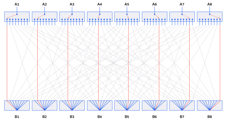
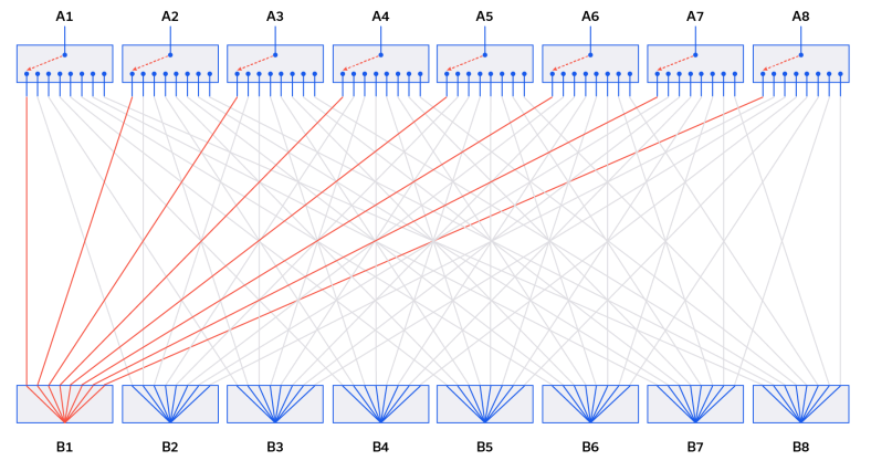
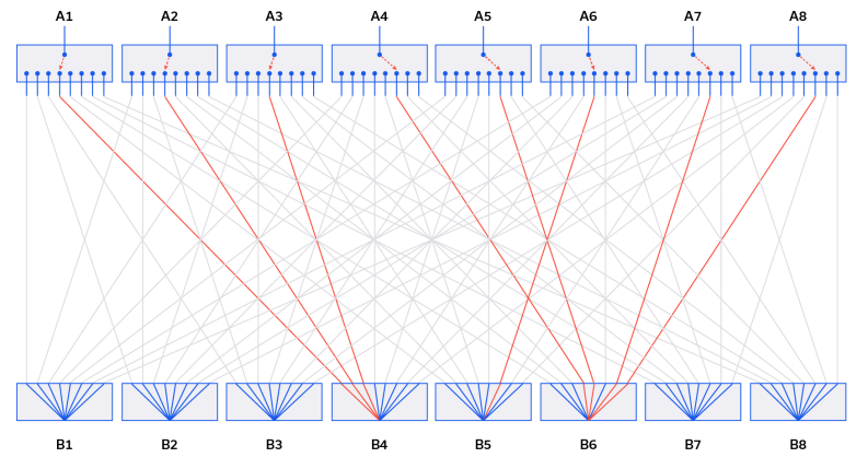
The example in Figure 1 is an 8×8 non-blocking configuration, allowing 8 paths to be active simultaneously in a range of possible configurations. The figures below demonstrate the flexibility of the non-blocking configuration, with Figure 2 showing a routing that could also be achieved in a blocking matrix, Figure 3 showing all inputs connected concurrently to the same output, and Figure 4 showing a combination of paths.
Benefits & Trade-Offs
The key advantage of a non-blocking matrix over a blocking version is the ability to have multiple ports connected to the same input / output at once. The use of splitters in place of switches for one bank can also help to reduce cost, since these components are typically lower cost than switches. The trade-off is that the use of splitter / combiner components can be limiting for the overall RF parameters of the matrix, typically resulting in higher insertion loss, limited isolation between ports routed into the same splitter / combiner, and a reduction in RF bandwidth.
Mini-Circuits has an industry-leading catalog of splitter / combiner components available with frequency ranges up to 65 GHz combined with the flexibility and in-house expertise to create non-blocking switch matrices for a wide range of applications.
Applications
The ability to combine multiple inputs concurrently into a single output or to share a single input into multiple outputs makes a non-blocking switch matrix configuration ideally suited to test applications based around wireless devices, or any other system based on a transmitter or receiver. Non-blocking matrices also provide the option to open up test resources by allowing multiple users or systems to share resources and run multiple tests in parallel.
For testing of a transmitter or signal source, it can be convenient to share the source to multiple devices or test stations. Routing the source into the input (splitter side) of a matrix makes the signal available to all devices / test stations connected at the outputs to the matrix, with each able to choose whether to connect that signal or a different one.
For receiver test applications the fan-in orientation may be advantageous, allowing multiple signal sources to be switched on and off in combination into the receiver DUT. This configuration allows the receiver to be evaluated in the presence of signals simulating multiple base stations for example, as well as co-located interfering signals.
Mini-Circuits’ Solutions
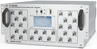
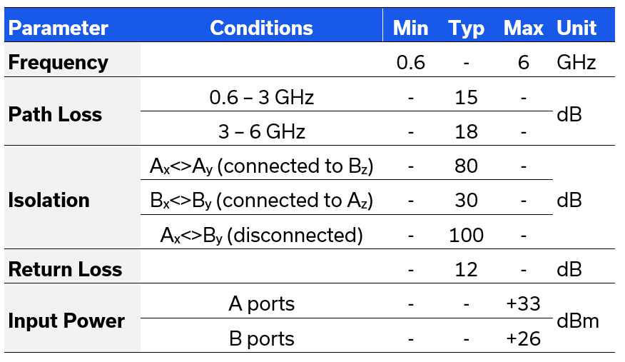
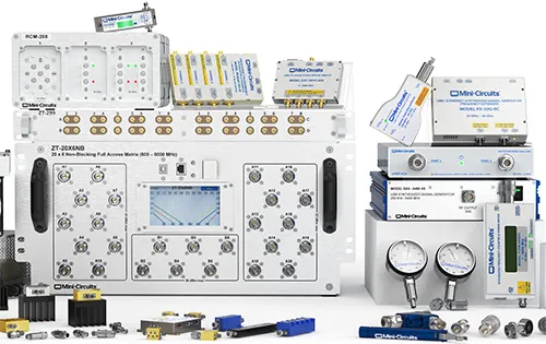
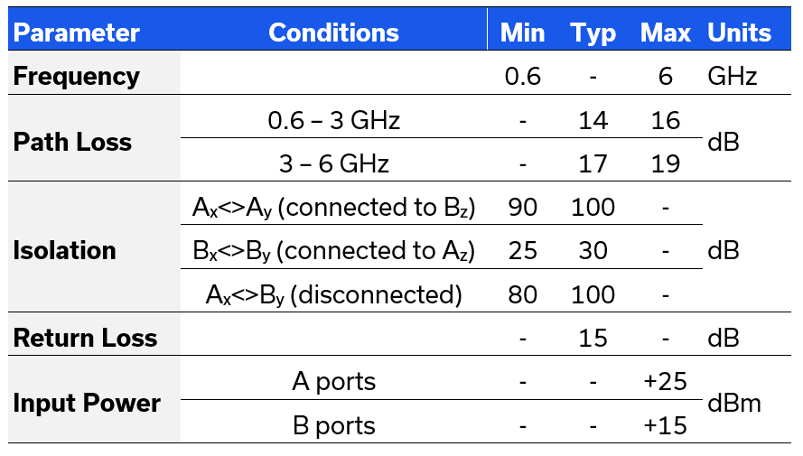
Two examples of Mini-Circuits’ non-blocking switch matrix designs are summarized below, both operating from 600 MHz to 6 GHz. ZT-8X8NB is an 8 x 8 matrix in a compact 3U rack chassis, developed using solid-state switches and passive splitter / combiners. ZT-20X6NB is a 20 x 6 matrix, with 20 inputs fanning out to 6 outputs, developed using a combination of solid-state and mechanical switches to gain the advantages of both. Both models can be controlled via Ethernet or USB, using the included GUI, or comprehensive API for automation in most modern programming environments.
ZT-8X8NB
- 8 x 8 non-blocking switch matrix
- 19” rack-mount chassis, 3U, 20” depth
- SMA female connectors (front & rear)
- Ethernet & USB control

ZT-20X6NB
- 20 x 6 non-blocking switch matrix
- 19” rack-mount chassis, 5U, 20” depth
- N-type female connectors (front)
- Ethernet, USB & touchscreen control
