Novel MMIC Splitter/Combiner Designs Achieve High Isolation Down to DC
Overview: Resistive vs. Wilkinson Power Splitter / Combiners
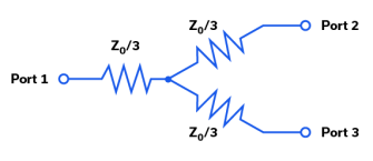
Traditionally, DC power splitter / combiner circuits are implemented with resistors. A simple resistive power splitter / combiner circuit schematic is shown in Figure 1. If Z0 = 50W, and ports 2 and 3 are terminated in 50W, then port 1 is matched to 50W as well, so Z0 / 3 = 16.7W. Resistive power splitter / combiner circuits typically have poor isolation between ports at DC and over frequency. In Figure 1, the isolation from any port to any port is equal to the insertion loss of the resistive power splitter / combiner, which is theoretically 6 dB at DC. The insertion loss for Figure 1 can be calculated assuming VIN is applied to Port 1, and Port 2 is the output voltage VOUT with both port 2 and 3 terminated in Z0:
VOUT = VIN [(4/3 Z0 ll 4/3 Z0) / {(4/3 Z0 ll 4/3 Z0) + (Z0/3)}] * [Z0/{Z0+(Z0/3)}]
VOUT = VIN (2/3) * [Z0/{Z0+(Z0/3)}]
VOUT = VIN (2/3) * (3/4)
VOUT = VIN (1/2)
VOUT / VIN = (1/2) = 20 log (1/2) = – 6 dB
Due to the symmetry of this particular circuit, the same equations apply to the calculation of the isolation from port to port. The calculated theoretical isolation is determined to be 6 dB. In real hardware and applications, additional sources of insertion loss will further impact the theoretical calculation.
As an example of the typical isolation at DC for resistive splitter / combiner designs, Figure 2 shows the measurements of insertion loss and isolation for Mini-Circuits’ ZFRS-2050+ resistive splitter / combiner. At DC, the measured insertion loss is approximately 6 dB, which is equal to the measured isolation. This measured performance represents the theoretical limit, as calculated above, for the isolation possible for a resistive power splitter / combiner. Since resistive splitter / combiner circuits do not include reactive components, the effective bandwidth of the resistive splitter / combiner will be limited by package and board parasitics. Depending on the absolute tolerance of the resistors used, the voltage standing wave ratio (VSWR) can be close 1.0 at low frequencies and provides an excellent match. Additionally, the gain and phase imbalance between ports can be quite low.

High frequency power splitter / combiner circuits are typically implemented using the Wilkinson power splitter / combiner circuit because these designs can achieve high isolation between output ports at high frequencies, whereas resistive designs traditionally cannot. A circuit schematic for the Wilkinson power splitter / combiner is shown in Figure 3. At port 1, there are two parallel quarter-wavelength transmission lines with characteristic impedance Z0 * √2. The wavelength l of the l / 4 transmission line is calculated from the following equation:
l = c / frequency
Where c = speed of light = 3.0 X 10⁸ meters / second
frequency = the design frequency in GHz
In Figure 3, there is also a differential termination resistance of 2 * Z0 across ports 2 and 3.
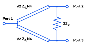
The theoretical insertion loss for the Wilkinson circuit from port 1 to either port 2 or 3, at the design frequency, can be calculated to be:
S21 = 20 log (1/ √2) = – 3 dB
The 3 dB difference in insertion loss between the resistive and Wilkinson splitter / combiners is caused by the extra voltage drops across the Z0 / 3 resistors in the resistive circuit. The Wilkinson power splitter / combiner also has better isolation than the resistive design at high frequencies. Figure 4 shows the measurements of the insertion loss and isolation for Mini-Circuits’ EP2C+ MMIC splitter / combiner which utilizes a Wilkinson design. The EP2C+ operates over the 1.8-12.5 GHz frequency range. Over the frequency range of interest, the measured insertion loss is 0.5 to 1.0 dB within the theoretical limit. The measured isolation over the same frequency range is 10 to 35 dB.

Some of the advantages of the Wilkinson splitter / combiner include the ability to be easily realized on a printed circuit board (PCB) using printed components such as PCB transmission lines on low loss PCB substrates. For lower frequency operation however, the size of the quarter wavelength transmission lines can become too large and costly to be practical. This limits the application Wilkinson designs to mostly microwave applications. Since the Wilkinson splitter / combiner is based on quarter wavelength transmission lines, the bandwidth is also limited. Wilkinson splitter / combiners also tend to have significantly poorer amplitude and phase imbalance. Therefore, designers typically face a tradeoff in product selection between the low-frequency coverage, bandwidth, and low unbalance of resistive designs, and the better insertion loss and isolation of Wilkinson designs at higher frequencies.
Mini-Circuits’ MMIC Resistive / Reactive Power Splitter / Combiners: The Best of Both Worlds
Mini-Circuits has developed a MMIC resistive / reactive power splitter / combiner family that combines the best attributes of resistive and Wilkinson designs. These products cover the frequency spectrum from DC to high frequencies, with insertion loss on the order of a resistive splitter / combiner, while having isolation performance at DC that rivals that of a high frequency Wilkinson design. EPxR-series splitter / combiners utilize patent-pending design techniques and Integrated Passive Device (IPD) process technology on Gallium Arsenide (GaAs) to achieve this unique performance.
This product performance is unparalleled in the industry as no competitive products exist with a similar combination performance attributes. This performance is exemplified in the following product part numbers from Mini-Circuits: EP2RCW+, EP2RKU+, and EP4RKU+. The measured insertion loss and isolation over frequency for the Mini-Circuits EP2RCW+ MMIC resistive / reactive power splitter / combiner is shown in Figure 5. The measured insertion loss over frequency for this model is close to that of the Mini-Circuits ZFRSC-2050+ resistive splitter / combiner shown in Figure 2. Meanwhile, the measured isolation performance is higher than the 6 dB isolation for the ZFRSC-2050+. The EP2RCW+ goes to DC with isolation performance better than the theoretical limit of a traditional resistive splitter / combiner. The measured gain and phase unbalance for the EP2RCW+ is comparable to that of the ZFRSC-2050+ resistive splitter / combiner as well.

The EP4RKU+ offers similar performance for a 4-way split, while the EP2RKU+ offers an even wider bandwidth from DC to 18 GHz. All models are available in standard over-molded QFN packaging and in bare die format.
Applications
Mini-Circuits’ MMIC resistive / reactive splitter / combiner designs offer greater versatilitythan traditional resistive and Wilkinson type splitter / combiners because of their unique performance characteristics. Figure 6 shows one application for a DC-coupled, high dynamic range application at baseband frequencies. Here, a single DC coupled amplifier splits the signal into multiple individual signal processing channels. This allows each channel to perform signal processing on the same signal independently. This architecture can be used for narrowband receivers that perform channelization filtering on a low IF / RF wideband signal in each channel. The EP4RKU+ can be used to perform further narrowband channelization with additional filters. The use of the EP2RCW+ or EP2RKU+ enables this architecture with low insertion loss and superior isolation performance, as well as good gain and phase matching compared to that of a resistive splitter.

Another common application to consider at higher RF frequencies is shown in Figure 7. This block diagram represents the transmitter signal path for a phased array radar. For this multi-channel RF application, RF automatic gain control (AGC) and phase shifters are required to adjust both the gain and phase of each individual signal path. This gain and phase adjustment for each channel is typically accomplished during calibration. The use of Mini-Circuits’ resistive / reactive splitter / combiners provides excellent gain and phase match at RF, and can potentially eliminate the need for additional gain and phase mismatch calibration in the signal channels.

Conclusion
Mini-Circuits has developed a unique resistive / reactive power splitter / combiner product family that combines the advantages of resistive and Wilkinson splitter designs. These products cover wide bandwidths from DC to 18 GHz while maintaining isolation performance comparable to that of a Wilkinson splitter / combiner over the entire range. These products offer advantages for many applications where designers may have been faced with performance tradeoffs in the past. Specs for these models are summarized below, and additional data are available on respective model dashboard pages at Minicircuits.com:
Resistive / reactive power splitter / combiner
| Model Number | Interface | No. of Ways | Freq. Range (MHz) | Isolation (dB) | Insertion Loss (dB) | Phase Unbalance (deg) | Amplitude Unbalance (dB) | Power Input (W) as Splitter, Max. |
| EP2RKU-DG+ | Die | 2 | DC-18000 | 23 | 2.9 | 0.6 | 0.1 | 0.6 |
| EP2RKU+ | SMT | 2 | DC-18000 | 26.1 | 3.3 | 1.1 | 0.02 | 0.3 |
| EP4RKU-DG+ | Die | 4 | DC-18000 | 23 | 4.8 | 0.9 | 0.2 | 0.6 |
| EP4RKU+ | SMT | 4 | DC-18000 | 18.8 | 3.8 | 1.9 | 0.2 | 0.6 |
| EP2RCW-DG+ | Die | 2 | DC-8000 | 22.3 | 4.5 | 0.1 | 0.1 | 0.6 |
| EP2RCW+ | SMT | 2 | DC-8000 | 23 | 4.8 | 0.9 | 0.02 | 0.3 |


