

TEST
SOLUTIONS
For test systems requiring distribution of signal to many DUTs, Mini-Circuits’ signal distribution systems combine splitter/combiners and directional couplers to expand test signal into multiple channels. Amplifiers can also be incorporated to minimize path loss and manage signal power from input to output.
Best viewed on desktop.
Please use the below filters to narrow down your search according to your required parameters.
You may also sort each column (alphabetic or numeric) by clicking on their header.
Fill out the form if you need help choosing a part, need samples or if you have any questions, and we will get back to you as soon as possible.
An RF signal distribution system expands a single test signal into many channels so it can feed multiple devices under test simultaneously. It combines splitter/combiners and directional couplers — and optionally amplifiers to offset path loss — into a single rack-mounted, panel-mounted, or benchtop structure. This replaces a tangle of individual components and cables with one organized, documented unit, which matters in high-volume production test where dozens of DUTs share a signal source.
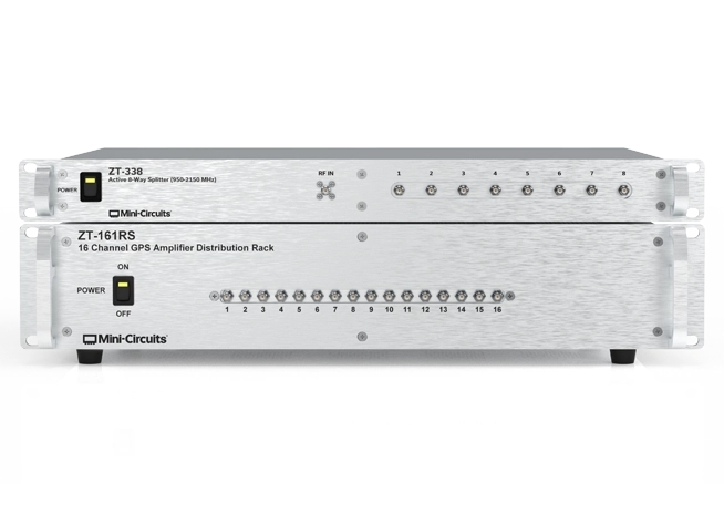
A passive splitter divides signal power among its outputs with no external power, so each output is inherently lower in level than the input — a 2-way split costs at least 3 dB, an 8-way at least 9 dB. An active splitter includes amplification to compensate for that loss, delivering outputs at or above the input level. In this catalog, the passive structures cover the bulk of the range, while active models include the ZT-161RS (16-way, 22 dB gain, 900–2250 MHz) and the ZT-415 (8-way, 1.5 dB gain, 30–6000 MHz). Choose active when split loss would drop your signal below the DUT’s usable level.
Three high-power splitters handle up to 100 W: the ZT-10HPS-272 (10-way, 700–2700 MHz), the ZT-16HPS-63W-S (16-way, 700–6000 MHz), and the ZT-20HPS-63-S (20-way, 2500–6000 MHz) — all 2U chassis with N-type and SMA connectors. Among the standard passive structures, many 4-way and 2-way panels handle 30 W per port, and the ZT-351 (4-way, 10–40 GHz) handles 20 W. Matching the power rating to your source output is essential, since exceeding it can damage the splitter.
The ZT-351 is the highest-frequency structure in the catalog, providing four 4-way splitter/combiners covering 10–40 GHz in a 1U panel with 2.92 mm connectors and 20 W handling. For broadband coverage below that, the ZT-256 offers twelve 2-way resistive splitter/combiners up to 18 GHz, and the ZT-429 offers twenty 2-way splitter/combiners up to 11 GHz. Custom wideband configurations beyond the standard catalog are available on request.
A resistive splitter uses a simple resistor network, giving extremely broad bandwidth (often from DC upward) and good port-to-port matching, but with higher loss — typically 6 dB on a 2-way split rather than the 3 dB of a reactive design — and no isolation between output ports. A reactive splitter uses transformers or transmission-line structures for lower loss and real isolation, but over a narrower band. The ZT-256 is the resistive option here (twelve 2-way splitters up to 18 GHz, 0.1 W), chosen when bandwidth matters more than loss.
A directional coupler taps off a small, precisely known fraction of the signal — leaving the main path largely undisturbed — so you can monitor or measure the signal without interrupting the test. This is how you feed a power meter or spectrum analyzer while the DUT continues to receive the main signal. The ZT-230 provides eight 10 dB directional couplers covering 1–500 MHz in a 2U panel with SMA connectors, meaning each coupled port carries a signal 10 dB below the through path.
Chassis units are enclosed rack-mount systems (1U–4U) housing the components internally with connectors on the panel — used where the structure includes active circuitry or needs protection. Panel structures mount the components directly on a 19-inch rack panel with all ports accessible on the face, which is the simplest and most serviceable option for passive networks. Benchtop units, such as the ZT-104, sit on the bench for standalone or portable use. Panel structures dominate this catalog because most distribution networks are passive.
For a single high-way split, the ZT-394 provides one 16-way splitter/combiner (600–6000 MHz, 30 W) in just 1U, and the ZT-20HPS-63-S provides a 20-way high-power split in 2U. For density of separate components, the ZT-201 and ZT-222 each hold twenty independent 2-way splitter/combiners (350–6000 MHz, N-type) in 4U, and the ZT-429 holds twenty 2-way splitters up to 11 GHz. Multiple independent splitters in one structure let you serve several unrelated signal paths from a single rack unit.
Fixed attenuator panels set a known, permanent level reduction in a signal path — protecting sensitive instruments from high-power sources, improving impedance matching, or bringing a signal into a DUT’s usable range. Four panels are offered: the ZT-354 (10 dB), ZT-358 (20 dB), and ZT-275 (30 dB), each with ten attenuators rated to 20 W and usable up to 18 GHz in a 2U panel; plus the ZT-337, with four 30 dB attenuators rated to 100 W up to 6 GHz in a 3U N-type chassis. Unlike programmable attenuators, these are fixed-value and passive.
Yes. Because Mini-Circuits keeps a wide selection of splitter/combiners and directional couplers in stock, custom distribution structures can be built to your specific channel count, frequency range, power level, connector type, and form factor — including versions with integrated amplifiers to minimize path loss from input to output. MCDI, the exclusive representative of Mini-Circuits in Israel, has an application engineering team that helps you specify the configuration, request samples, and get local support. Reach MCDI at 077-5406075, via the website contact form, or on WhatsApp.




Before you leave, you should know that MCDI’s professional team of Application Engineers will be delighted to assist you in sourcing the right component. Just fill the form and we will be back to you shortly.