Wideband Connectorized Amplifiers for mmWave Over-The-Air (OTA) Transmitter & Receiver Testing

The advent of 5G networks has already begun ushering in a whole new generation of wireless devices and applications, and device manufacturers are racing to be the first market. In order to meet the 5G standard for commercial wireless communication, device manufacturers need to develop powerful transmitters and receivers that operate in the millimeter wave range, which comes with a number of challenges, one of which is testing and qualification. Due to the wireless nature of these devices, manufactures need to conduct testing in real-world conditions, which isn’t possible using the conventional approach of connecting devices under test (DUTs) to instruments with coaxial cables. Over-the-air (OTA) allows engineers to more realistically simulate real-world device performance in the lab environment.
Distributed RF Amplifier Designs for Ultra-Wideband Applications
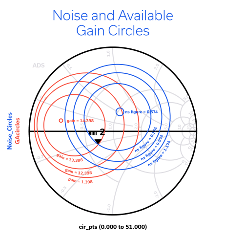
Amplifiers are used in RF systems to boost the power level of a signal. Conventional RF amplifiers are designed using reactive elements to achieve matching to the characteristic impedance of a circuit within the specified operating frequency range for a given system. Reactively matched amplifiers allow designers to optimize performance parameters for a broad range of system requirements. Combined with techniques like balancing, using 90˚ hybrids and negative feedback, they can support bandwidths as wide as about 10:1.
MMIC Amplifiers with Shutdown and Bypass Features De-Mystified
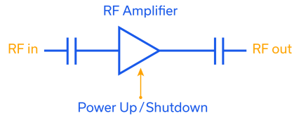
Mini-Circuits’ TSS- and TSY-families of MMIC amplifiers feature a versatile combination of performance characteristics including high dynamic range and very low noise figure with wideband frequency coverage from VHF up to mmWave applications. These product families also include additional features of shutdown and bypass functionality. These features often lead to customer questions about the difference between bypass and shutdown, which products have which features, and the benefits of each. This article will explain how these features work, and provide an overview of some of the applications are where shutdown and bypass functions are most commonly used.
MMIC Technologies: Pseudomorphic High Electron Mobility Transistor (pHEMT)

Pseudomorphic High-Electron-Mobility-Transistor (pHEMT) is one technology Monolithic Microwave Integrated Circuit (MMIC) designers and fabs use to develop and manufacture microwave integrated circuits. pHEMT has gained popularity as a building block of many MMICs produced by electronics manufacturers like Mini-Circuits due to its superior wideband performance characteristics including low noise figure, high OIP3 and excellent reliability up to 40 GHz and beyond. pHEMT uses heterojunctions between semiconductors of different compositions and bandgaps to achieve outstanding high-frequency performance. This article delves into the physics of pHEMT operation, advantage, and reliability test results. A link to a summary of Mini-Circuits’ pHEMT products is also provided.
Positive Gain Slope Amplifiers Compensate for Gain Roll-Off in Wideband Systems
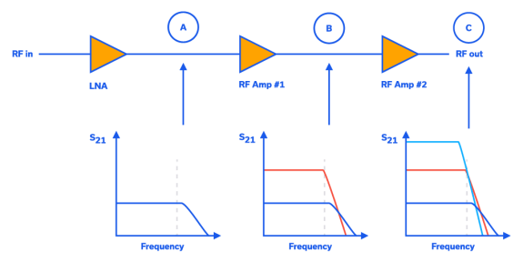
Meeting gain roll-off and gain flatness requirements over frequency is a common problem in many modern-day discrete RF transceivers. Ideally, the gain in the signal path of an RF transceiver should be flat over frequency in the band of interest. However, each component in the RF line-up has a finite bandwidth, which can cause the overall system gain response to roll-off over frequency. This is seen as negative slope in a graph of gain versus frequency. This behavior makes meeting gain flatness specifications for these transceivers very challenging to achieve, particularly over wide bandwidths.
Best Practices for Additive Phase Noise Measurements in Amplifiers

This article will review the challenges in measuring additive phase noise in Amplifiers and present details of the measurement setup Mini-Circuits uses to perform these measurements accurately and reliably. We will also dive into the specifics of additive phase noise readings and explain how to interpret phase noise values and measurement plots.
A Primer on RF Semiconductors (MMICs)
A Primer on RF Semiconductors (MMICs) Radhakrishna Setty, Technical Advisor Introduction Semiconductors are ubiquitous in modern society. In addition to microprocessors for computing technologies, they are used in practically every active wireless communications system including cell phone towers, cell phones, radars and satellites to name a few. Mini-Circuits designs and produces several semiconductor-based (MMIC) components […]
Understanding RF Power Amplifier Classes
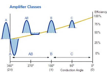
Power amplifiers (PAs) boost input signals using different amplification schemes depending upon application requirements and the nature of the signals to be boosted. Signals may be continuous wave (CW) or many forms of pulsed waveforms, with different pulse widths and duty cycles. Different signal types have different amplification needs in terms of output power, gain, efficiency, linearity, and other performance parameters.
Advanced Microwave Amplifier Models for Advanced Design System Simulations

Mobile and wireless communication has seen phenomenal growth over the past two decades. Faster communication with higher data rates has been the driving factor. To achieve this, the RF front end components have been continuously improved to meet the linearity and power requirements and a range of wireless standards have emerged, based on variations in frequency, modulation and power level requirements. The 0.7 GHz to 6 GHz band has been the mostly widely used frequency range for mobile and wireless communications using different standards such as GSM, CDMA, WCDMA, LTE, WLAN and WiMAX. The evolving 5G standard is pushing frequency ranges for emerging commercial systems upward to mm-wave frequencies as high as 86 GHz! Still, the bulk of near term 5G developments will likely be at the proposed bands of 28GHz and below.
Compensating Frequency-Dependent Cable Loss in CATV Systems with Mini-Circuits Voltage-Variable Equalizers
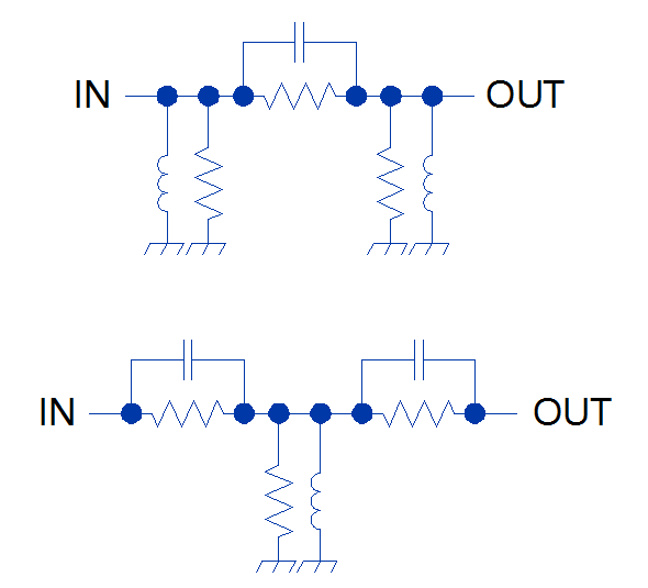
In broadband communications systems such as CATV equipment, system performance may critically rely on gain or attenuation flatness. In particular, CATV systems are often plagued by issues resulting from the frequency-dependent attenuation of very long cables (increasing with frequency) as well as the negative gain slope of certain amplifiers. This negative gain slope exhibited by CATV system components can cause a variety of headaches for system designers.


