Frequently Asked Questions About Power Detectors

Frequently Asked Questions About Power Detectors
Q. I recently purchased a PWR-6G power detector and was wondering if I need to have it calibrated, or if it came to me calibrated.
A. The PWR-6G+ is calibrated prior to shipping and therefore there is no need for calibration of new power detectors. A customer can start working once the power sensor software has loaded and the USB cable is plugged in to the computer. We recommend sending the PWR-6G+ once a year for calibration.
Ultra-Wideband, Low-Loss Couplers for Cable TV and Broadband Access Systems (DOCSIS® 3.1)

This article discusses the use of ultra-low loss, broadband distributed couplers in 75Ω systems such as broadband services over cable television networks (CATV).
Demystifying Pin-Outs: What Do We Mean by “Not Connected?”
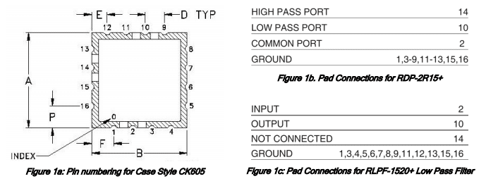
Mini-Circuits offers a wide range of products in miniature surface-mount (SMT) packages. Each package is identified by a case style number and defined by a case style drawing which clearly shows the outline dimensions, critical dimensions (if any), orientation, pin numbering, pin-out details, and material finish wherever applicable.
Some case styles are used in various Mini-Circuits products, and different signal pads may be used depending on the circuit design of each model. In some cases, some signal pads on the unit may be left unused and marked as “NOT CONNECTED” in the pin-out details on the datasheet.
This article explains by way of example what we mean when we denote signal pads this way, and how users may treat these pads when mounting the part on their board.
הקטנה עד למינימום של אי תיאום עכבות בעזרת מנחתים קבועים

מנחתים קבועים הם התקנים יקרי ערך שפותרים בעיות למתכננים ברמת המעגל ולמתכננים ברמת המערכת. בנוסף לשליטה על רמות המשרעת (אמפליטודה), מנחתים קבועים יכולים לשפר את תיאום העכבות בין התקנים שיש להם רגישות לעכבה (אימפדאנס), כגון מגברים ומסננים ולספק את הבידוד הנדרש לייצוב מתנדים.
MMIC Amplifiers Stretch the Boundaries of Dynamic Range in VHF/UHF Communications

The noise figure and linearity of low noise amplifiers are critical factors in maximizing sensitivity and dynamic range in RF receiver design. The amplifier noise figure determines the weakest signal the amplifier can discern, and the IP3 determines the degree to which intermodulation products from nearby signals interfere with the desired signal. The lower the noise figure and the higher the IP3 of the amplifier at the receiver input, the greater the sensitivity and Spurious Free Dynamic Range (SFDR) of the receiver.
Understanding Surface-Mount
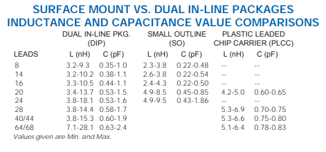
The main reason for the utilization of surface mount technology today is for PWB area efficiency and the corresponding reduction of the system volume. Small surface mount components are used to manufacture electronic assemblies that are significantly smaller than the similar function assemblies using thru-hole components. Usually, the board area for most systems can be reduced by a factor of two for a single sided board. When components are mounted on both sides of the board, size reduction by another factor of two can be achieved. Conversely, the functional density can be doubled in the same area with the use of surface mount components. Since the height of surface mount components are generally smaller, significant reduction in system volume can also be achieved. Fewer, denser assemblies and correspondingly fewer connectors, less mechanical hardware and shorter lead lengths can yield another reduction factor of 2 to 4. Add to that the use of Application Specific IC’s (ASIC’s), and a total volume amounting to approximately 20% of the original system can result.
Interface Dimension Measuring Gauge
Mini Circuits manufactures a comprehensive line of connector gauges for measuring the critical interface dimensions of coaxial connectors .Testing the interfaces of connectors on any device at incoming inspection is not only highly recommended, it is definitely a necessity. Interfaces not meeting the specifications will lead to degraded specification of the components. In addition, these out of specification interfaces may damage the connectors of mating components or ruin the connectors of the test equipment. These connector gauges consist of an exclusively developed dial indicator with appropriate bushings and pins, designed to mate with the specific connector under test. The indicator is set to zero by a calibration block (master).When engaged to a connector, it measures the specific interface dimension from a reference plane.
טכניקות לשיפור של אי תיאום עכבות
תיאום עכבות הוא נושא מורכב עטור מידה מסוימת של מסתוריות. כאשר נתקלים בתקלה במעגל או בבעיות מערכתיות, ברוב רובם של המקרים מייחסים את הסיבה לאי תיאום בעכבות. לכן, קיימים מקרים רבים שבהם יש צורך להתאים את העכבה של העומס לעכבה של מקור האות על מנת להגדיל למקסימום את העברת ההספק. קיימות טכניקות שונות ורבות להגיע לתיאום העכבות, והשימוש הטוב ביותר בכל אחת יהיה תלוי במצב. מאמר זה יסקור את עקרונות הבסיס של תיאום עכבות ויתאר כמה מהטכניקות היעילות שמשמשות בדרך כלל, על מנת להתגבר על אי תיאום עכבות במעגל.
פתרונות בעלות סבירה לבדיקת התקנים ל- 28 גה”צ מדור 5 עם מכשור מעבדה ל- 6 גיגה הרץ
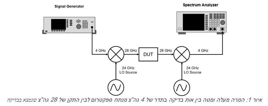
ליכולות המגדירות את התקן האלחוטי של דור 5 יהיה צורך בשימוש ברוחבי פס רחבים יותר, על פני אזורי ספקטרום רבים יותר, מאשר נדרש לכל טכנולוגיה אלחוטית קיימת. התקשורות בדור 5 ינצלו בסופו של דבר, פסים מרובים החל מתחת ל- 6 גה”צ ועד מעל ל- 60 גה”צ. לעת עתה, חלק ניכר ממאמצי הפיתוח מחולקים בין רוחבי פס של מתחת ל- 6 גה”צ עבור קישוריות בין כלי רכב ושידורים בטווח רחוק יותר, ופסים ברוחב 26, 28, 38 ו-60 גה”צ עבור יישומי פס רחב ניידים משופרים. ההגירה לתדרים גבוהים יותר וטבעו של הפס המרובה של הטכנולוגיה, מציבים מגוון של אתגרים ייחודיים עבור מתכננים שמפתחים התקנים וציוד רשת לדור 5. הגורם המשמעותי בין כל אלו הוא העלות הגבוהה של המכשור המשמש לבדיקות ומדידות על פני טווח כה רחב של תדרים.
ההשפעה של הגבלות זמן קוד תאריך יצור (Date Code) על האיכות, השירות והערך
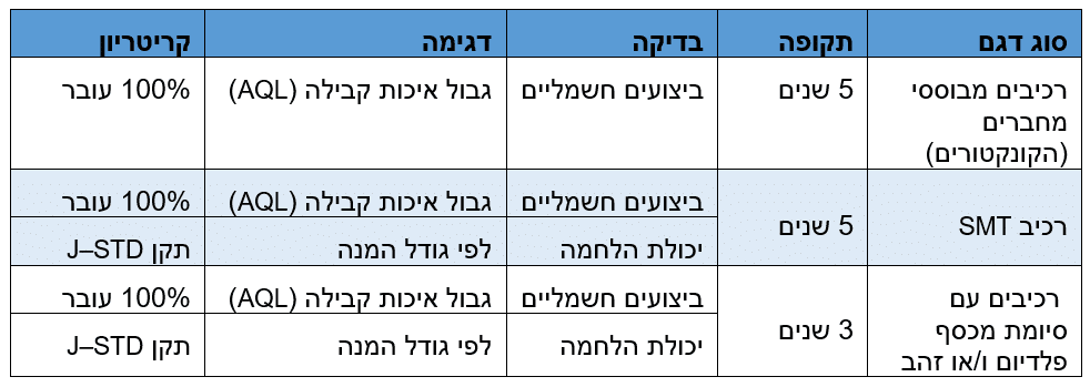
מחקר מקיף שנערך על ידי גופים מובילים בתעשייה, NASA וצבא ארה”ב מציג עדות מהותית לכך, שבתנאי הסביבה הקיימים באחסון המודרני, מרווחי זמן של 5 שנים ויותר בין תאריך הייצור של הרכיבים לבין מועד המשלוח ליצרני אלקטרוניקה (OEM), למעשה אינם מציבים כל סיכון בפני האיכות או האמינות של מוצרים אלקטרוניים. הגבלות הזמן המבוססות על קוד תאריך ייצור הרכיב, נוצרו כתוצאה מחששות שהיו קיימים לגבי התחמצנות הנובעת מהזדקנות של חלקים איטקטיים (שניתכים בהלחמה) או של חלקים מצופים בדיל, וכן לגבי איבוד יכולת ההלחמה של רכיבים. השינוי שהגיע לאחר מכן, שבא לידי ביטוי בהחלפת הלחמת מוליכים בבדיל בהלחמה ללא בדיל בחלקים תואמים להוראת RoHS, הקטין למינימום את המנגנון שהוביל לתקלה זו. בנוסף, ההתקדמות שחלה בתפיסת מארזי מוצרים ואחסונם, למשל אריזה, הצבה בסרט וטכניקות בקרת לחות, מספקת כיום הגנה קשיחה מפני פגיעה בביצועים האלקטרוניים ומפני תקלות שמופיעות “עם השליפה מהאריזה” שנובעות מהזדקנות, לתקופות זמן בסדר גודל של עשרות שנים. כתוצאה מהממצאים האלו, צבא ארה”ב ביטל לחלוטין את דרישות קוד תאריך הייצור עבור מוצרים אלקטרוניים, ו- NASA הקלה באופן משמעותי מאוד בתקנים שלה, והיא מאפשרת מעתה חלון זמן של 5 שנים בטרם תידרש סקירה של חלקים שנמצאים באחסון, על מנת לקבוע אם יש צורך בבדיקת סינון מחודשת שלהם.


