Understanding Suspended Substrate Stripline Filters
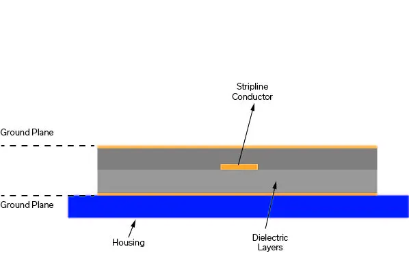
To manage signal purity in communications and test systems, no component is more important than RF filters. To meet the needs of these advanced systems, Mini-Circuits’ suspended substrate stripline filter products offer state-of-the-art performance featuring unique passband, stopband characteristics and outstanding reliability in harsh operating environments. The range of available filter types supports the needs of military, aerospace and commercial systems, including instrument systems, ultra-broadband receivers, laboratory testing, 5G and many other wideband communications systems.
Every Block Covered: Noise and Signal-to-Noise Ratio (SNR) in a 26 GHz 5G Front-End

The 24.25 to 27.5 GHz frequency range is also known as the “wider 26 GHz band” or 5G band n258. The Australian Communications and Media Authority (ACMA) “recognized that the wider 26 GHz millimeter wave (mmWave) band was at the forefront of the delivery of mmWave 5G wireless broadband services globally.”2 Consequently, in April 2021, a major portion of that spectrum was auctioned off to operators, predominantly in the 25.1 to 27.5 GHz frequency range.2 The 24.25 to 24.7 GHz band was identified for indoor use and the 24.7 to 25.1 GHz band for indoor/outdoor use.2 For the purposes of the RF front end in this application note, our focus will be on this lower, 24.25 to 25.1 GHz portion of the Australian 5G frequency range.
Reflectionless Filters Eliminate Spurs & Intermods

Mini-Circuits’ reflectionless filters are the only commercially available filters that absorb and internally terminate stopband signals rather than reflecting them back up the signal chain. Based on a novel, patented filter topology and produced with Mini-Circuits’ industry-leading MMIC design and manufacturing capability, these devices are a revolutionary solution to a number of unwanted effects related to embedding conventional filters in system designs. Our customers are finding innovative ways to achieve new levels of performance with these revolutionary products. Learn more below, and be sure to check out our full selection to see what they can do for your design!
Mini-Circuits helps the Quantum Computing Revolution
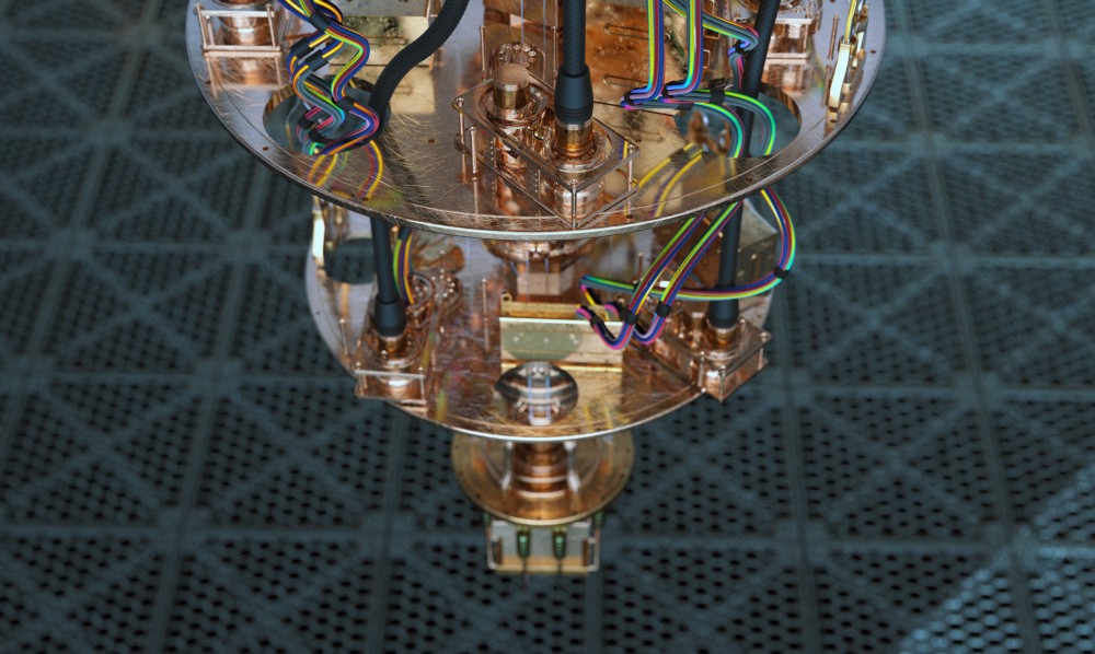
Most applications for Mini-Circuits products fall within traditional markets for RF/microwave components: telecommunications, aerospace and defense, test and measurement instrumentation, CATV, and broadband optical networks. But at the outer frontiers of science and engineering, the newest and most innovative work tends to cross boundaries between disciplines. For example, some of the most advanced research in climatology stems from collaboration between meteorologists and mathematicians. Molecular biologists team up with computer scientists to develop new treatments for chronic diseases. Likewise, the race to build the world’s first useful quantum computer has drawn on applied knowledge from physics, computer science, and RF/microwave engineering. This revolutionary technology is among the more exotic applications of Mini-Circuits products and also one of the most advanced on the continuum of scientific progress.
Linearity – Cascaded P1dB and IP3 for a Simple Microwave Front-End
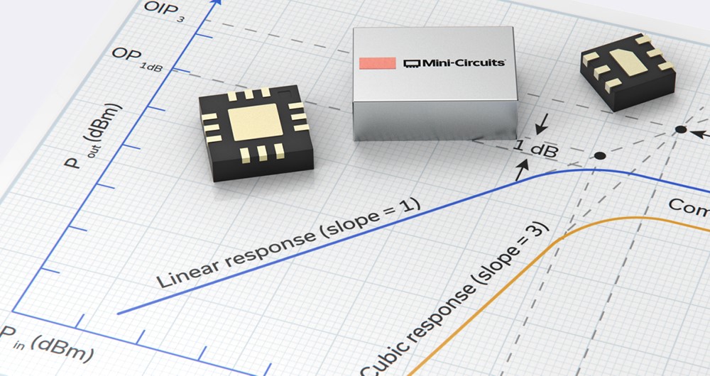
When examining a device data sheet, linearity parameters P1dB and IP3 are straightforward and relatively easy to apply during the design process. Once several components are connected in series in a design, complex equations governing cascaded P1dB and IP3 must be utilized to determine the overall linearity performance of the system or subsystem. The equations utilized to compute P1dB and IP3 provide a means of achieving accurate results in the absence of expensive simulation software. Even though the effect of VSWR interactions between stages is not included when performing the calculations, the results are a good first order approximation of the cascaded performance of the system. The purpose of this application note is to review P1dB and IP3 in general, and to compute these parameters for a basic, three-component RF front end. Other application notes in this series will delve further into the cascading of P1dB and IP3 as the system includes additional nonlinear components such as those utilized in frequency conversion and the accompanying IF components.
MMIC Technologies: Integrated Passive Devices (IPD)
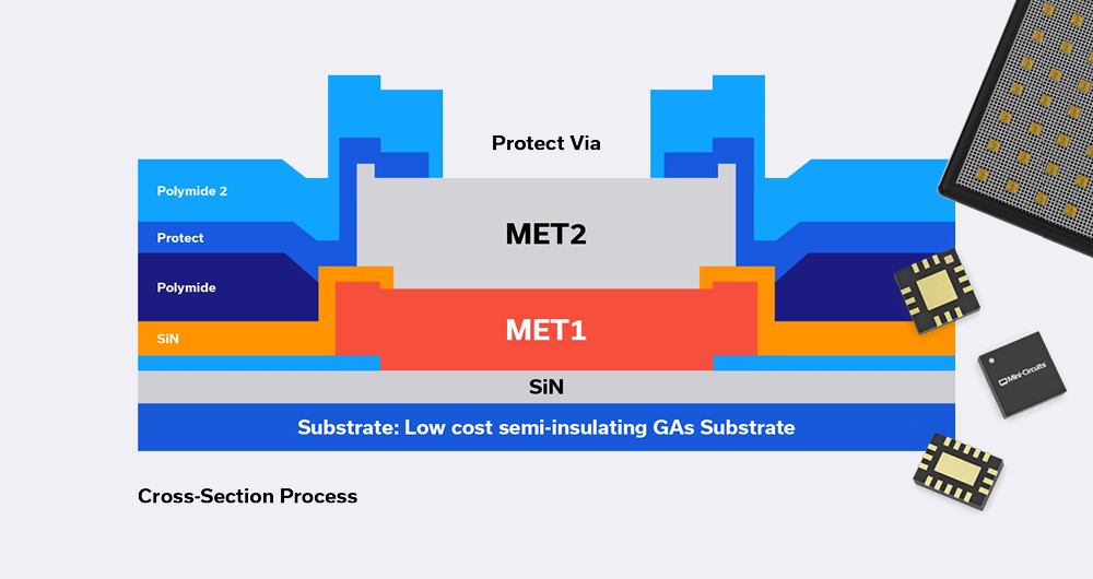
Monolithic Microwave Integrated Circuits (MMICs) with no active elements such as transistors, and containing only passive elements such as resistors, capacitors, inductors, are referred to as Integrated Passive Devices (IPD). These devices do not need DC power to operate, and do not perform frequency conversion as in the case of frequency mixers or frequency multipliers.
What’s the big deal about IPDs? The short answer is they perform vital functions which active elements cannot such as filtering, equalization, balanced-to-unbalanced line conversion (or vice versa) and many more as we will describe later.
Every Block Covered: Noise and Signal-to-Noise Ratio (SNR) in a Simple Microwave Front-End
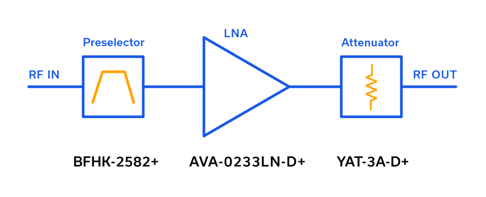
When a technical discussion turns to noise, especially with several cascaded components involved, the calculations and terminology should be straightforward, but often they become more cumbersome than necessary. Signal-to-noise ratio (SNR) is another parameter that should be routinely calculated by the designer but that still creates uncertainty. The purpose of this short applications note is to square-up noise, noise floor, bandwidth and signal-to-noise ratio (SNR) in general, and to compute these parameters for a basic, three-component RF front end. Other application notes in this series dive deeper into the cascading of noise figure (NF), P1dB and IP3.
Using LTCC Thru-Lines as Filter Placeholders
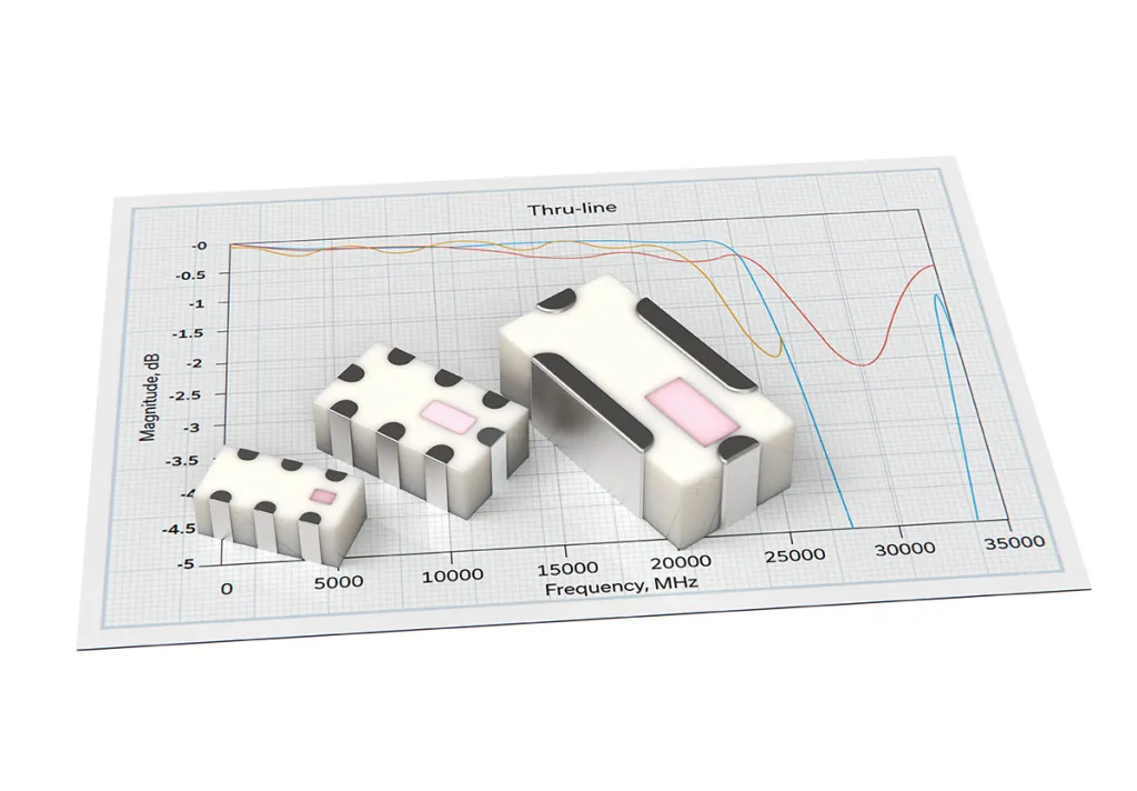
Experienced engineers often take some creative license inserting filters into component cascades to filter out a myriad of undesired signals. For example, mixer spurs at the IF port can be complex, and it’s difficult to predict the net effect of the IF filter on these undesired signals. Often, engineers will first examine the raw, unfiltered mixer spurs in detail as a test to choose the appropriate IF filter. The savviest of these engineers understand the importance of having thru lines in their repertoire with standard footprints to serve as placeholders for filters they may choose to add to the signal chain later in the design process. Sometimes, PC board footprints for filters are added as risk mitigation. In cases where no filtering is ultimately required, thru lines are inserted into these slots to stay.
A Short Primer on RF / Microwave Power Sensors
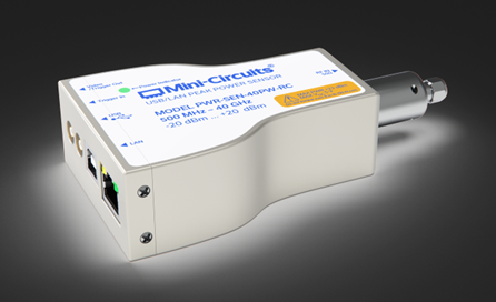
Proper power measurement techniques are important for achieving accurate results. Mini-Circuits’ PWR-series of smart power sensors now furnishes the measurement professional with the ability to make accurate peak and average measurements of CW, modulated, and pulsed RF signals at a more cost-effective price point than generally available anywhere else in the industry. Whether it’s a high dynamic range solution or a high frequency solution to 40 GHz, Mini-Circuits offers a power sensor to suit most RF/microwave engineering needs and budgets.
Mini-Circuits’ lineup of entry-level power sensor products capable of CW and true RMS measurements presents an economical option for applications requiring the measurement of CW signals to 8 GHz and modulated or multitone signals to 6 GHz. Both CW and true RMS power sensors and can be found on our main smart power sensors page.
Understanding Ceramic Coaxial Resonator Filters
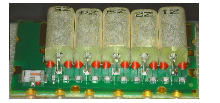
Jacques and Pierre Curie discovered the piezoelectric effect in 1880-1881, but it would take another century for the predecessor to the modern-day ceramic coaxial resonator-based filter to be designed and described.1 Over the course of that century, and in the decades that followed, advances in materials science and manufacturing technology enabled the primitive ceramics discovered in the 1940s2 to evolve into the compact, temperature-stable, rugged, and complex bandpass filter solutions of the 21st century. Mini-Circuits boasts one of the strongest portfolios of ceramic coaxial resonator filters anywhere in the world, with unparalleled availability to 6 GHz.


