Navigating Amplifier Thermal Analysis
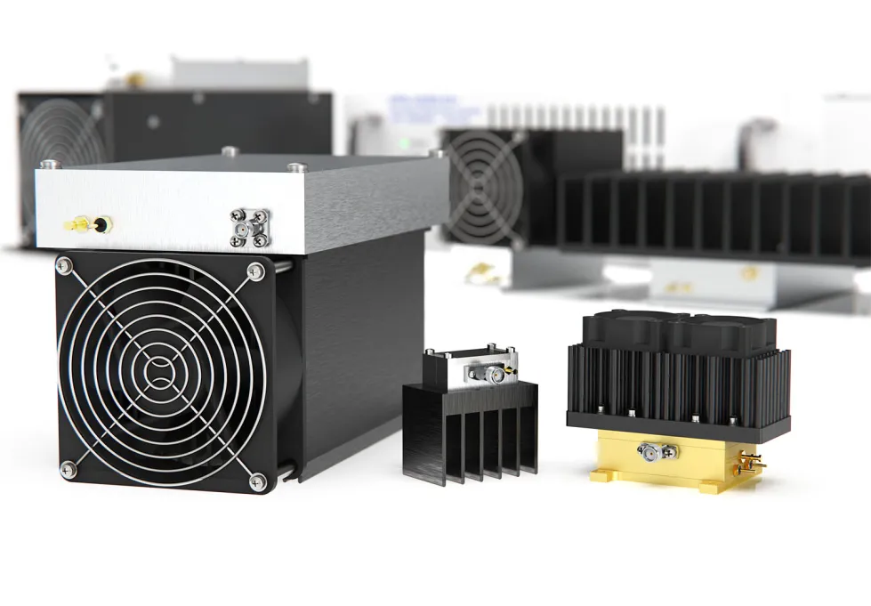
Mini-Circuits has a longstanding legacy of fully specifying the thermal performance of our amplifiers, with or without a Mini-Circuits-supplied heatsink. Recently, it has become so commonplace for custom heatsinks to be utilized with Mini-Circuits power amplifiers that the power amplifier thermal characteristics are now expressed differently. Although the thermal resistance of the Mini-Circuits-supplied heatsink is no longer explicitly provided for newer models this is easily calculated from the specifications given for any model power amplifier. Basic calculations are all that is needed to arrive at any parameter of interest when analyzing thermal characteristics of any Mini-Circuits power amplifier.
RF/Microwave Equalizers: An Essential Ingredient for the Modern System Designer

The need for equalization has become commonplace throughout the RF/microwave/millimeter wave frequency ranges. Modern military, satellite and wireless communications systems transmit and receive signals with relatively high instantaneous bandwidths. Gain variation across the signal bandwidth induces distortion in the transmitted or received signal because not all frequency components are amplified equally1. In other words, for multi-phase, multi-amplitude-level-modulated systems, unintended amplitude differences (i.e. due to gain changes) over the occupied bandwidth introduce errors, leading to incorrect interpretation of the signal and an increase in system bit error rate (BER)2
A Quick Guide to Mixer Topologies
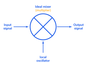
Real-world mixers come in many flavors. Mini-Circuits offers hundreds of unique mixer models representing six different circuit topologies. The good news is that this variety gives designers options for just about every application requirement. The problem, albeit a high-class problem, is that understanding the differences between mixer designs can complicate the component selection process.
This article will provide a broad overview of the different mixer topologies, including both balanced and unbalanced architectures. It should be noted that, in theory, any nonlinear device can be used to make a mixer, but Schottky diodes and Field Effect Transistors (FETs) are the most common. Mini-Circuits designs both diode- and FET-based mixers, but the topologies here will be presented using diode mixers for simplicity. However, the same principles can be applied to other technologies as well.
Wideband Connectorized Amplifiers Support Over-The-Air (OTA) Transmitter & Receiver Testing for 5G FR2 Bands

The advent of 5G networks has already begun ushering in a whole new generation of wireless devices and applications, and device manufacturers are racing to be the first to market. In order to meet the 5G standard for commercial wireless communication, device manufacturers need to develop powerful transmitters and receivers that operate in the millimeter wave range. This comes with a number of challenges, one of which is testing and qualification. Due to the wireless nature of these devices, manufacturers need to conduct testing in real-world conditions, which isn’t possible using the conventional approach of connecting devices under test (DUTs) to instruments with coaxial cables. Over-the-air (OTA) testing allows engineers to more realistically simulate real-world device performance in the lab environment.
A Quick Guide to RF & Microwave Filter Topologies
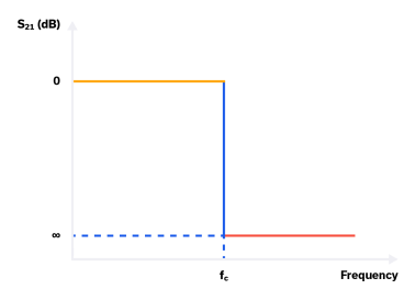
RF / microwave filters are essential building blocks of practically every wireless transceiver design. Filters block undesired signals outside the application operating bandwidth while passing in-band signals through to the rest of the signal chain. At a high level, filters can be described by their response, that is, the general shape of the S21 curve in the passband, transition, and stopband. A theoretically ideal filter would have a “brick wall” response, exhibiting 0 dB insertion loss in the passband, infinite rejection beyond the frequency cut-off fc and a transition from the passband to the stopband in 0 Hz
Choosing an LNA for your Receiver Front End
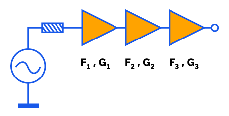
A low-noise amplifier (LNA), which Mini-Circuits defines as any amplifier with a noise figure (NF) below 3 dB, should usually be used at the front end of an RF or microwave receiver chain for ideal performance. This single component has outsized effects on the rest of the signal chain, and that’s why choosing an LNA is such a critical decision. Mini-Circuits stands ready to help our customers through this process, so let’s take a look at what goes into it.
Wideband Connectorized Amplifiers for mmWave Over-The-Air (OTA) Transmitter & Receiver Testing

The advent of 5G networks has already begun ushering in a whole new generation of wireless devices and applications, and device manufacturers are racing to be the first market. In order to meet the 5G standard for commercial wireless communication, device manufacturers need to develop powerful transmitters and receivers that operate in the millimeter wave range, which comes with a number of challenges, one of which is testing and qualification. Due to the wireless nature of these devices, manufactures need to conduct testing in real-world conditions, which isn’t possible using the conventional approach of connecting devices under test (DUTs) to instruments with coaxial cables. Over-the-air (OTA) allows engineers to more realistically simulate real-world device performance in the lab environment.
Distributed RF Amplifier Designs for Ultra-Wideband Applications
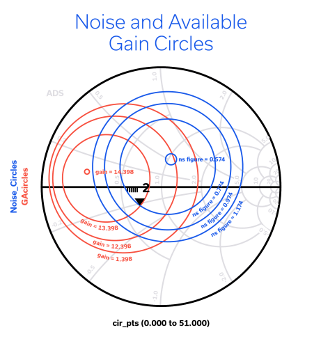
Amplifiers are used in RF systems to boost the power level of a signal. Conventional RF amplifiers are designed using reactive elements to achieve matching to the characteristic impedance of a circuit within the specified operating frequency range for a given system. Reactively matched amplifiers allow designers to optimize performance parameters for a broad range of system requirements. Combined with techniques like balancing, using 90˚ hybrids and negative feedback, they can support bandwidths as wide as about 10:1.
Novel MMIC Splitter/Combiner Designs Achieve High Isolation Down to DC
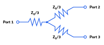
Traditionally, DC power splitter / combiner circuits are implemented with resistors. A simple resistive power splitter / combiner circuit schematic is shown in Figure 1. If Z0 = 50W, and ports 2 and 3 are terminated in 50W, then port 1 is matched to 50W as well, so Z0 / 3 = 16.7W. Resistive power splitter / combiner circuits typically have poor isolation between ports at DC and over frequency.
MMIC Amplifiers with Shutdown and Bypass Features De-Mystified
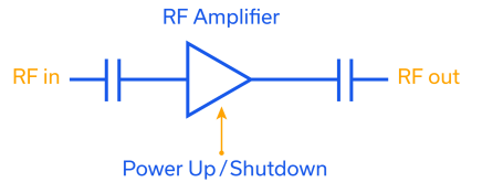
Mini-Circuits’ TSS- and TSY-families of MMIC amplifiers feature a versatile combination of performance characteristics including high dynamic range and very low noise figure with wideband frequency coverage from VHF up to mmWave applications. These product families also include additional features of shutdown and bypass functionality. These features often lead to customer questions about the difference between bypass and shutdown, which products have which features, and the benefits of each. This article will explain how these features work, and provide an overview of some of the applications are where shutdown and bypass functions are most commonly used.


